Low cost antenna design for wireless communications

a low-cost, wireless communication technology, applied in the direction of resonant antennas, elongated active elements, antenna earthings, etc., can solve the problems of increasing restrictions on the space available for a given antenna element, and increasing the problem of antenna installation space restrictions

Active Publication Date: 2008-11-20
INTEL CORP
View PDF2 Cites 99 Cited by
  • Summary
  • Abstract
  • Description
  • Claims
  • Application Information

AI Technical Summary

Problems solved by technology

For example, antenna installation space restrictions are becoming increasingly problematic due to the limited locations available to install additional antennas for added cellular coverage, especially in urban areas.
Also, antenna arrays for providing beam steering or beamwidth adjustment are being deployed and these require several antenna elements, creating further restrictions on the space available for a given antenna element.

Method used


Image

  • Low cost antenna design for wireless communications
  • Low cost antenna design for wireless communications
  • Low cost antenna design for wireless communications

Examples


Embodiment Construction

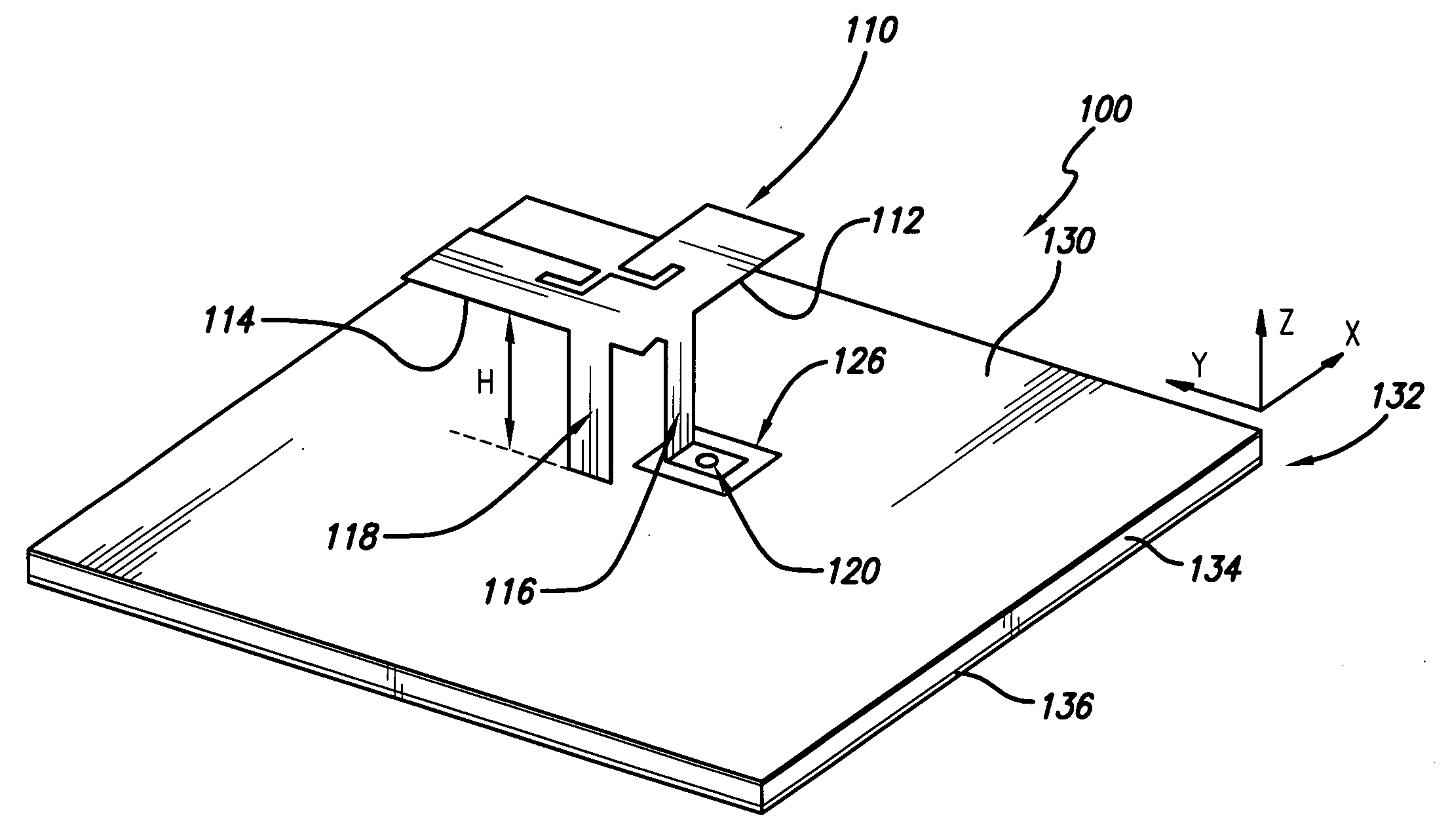
[0022]The present invention provides a simple and low cost antenna design. In a preferred embodiment, the antenna dimension is less than half of a patch antenna. The antenna can be either linear or circular polarized, and can be either single band or dual band. Also, only one feeding port is needed. Because of its small dimension and multiple features, the present invention is particularly useful in applications where only a small antenna space is available and in active antenna array application.

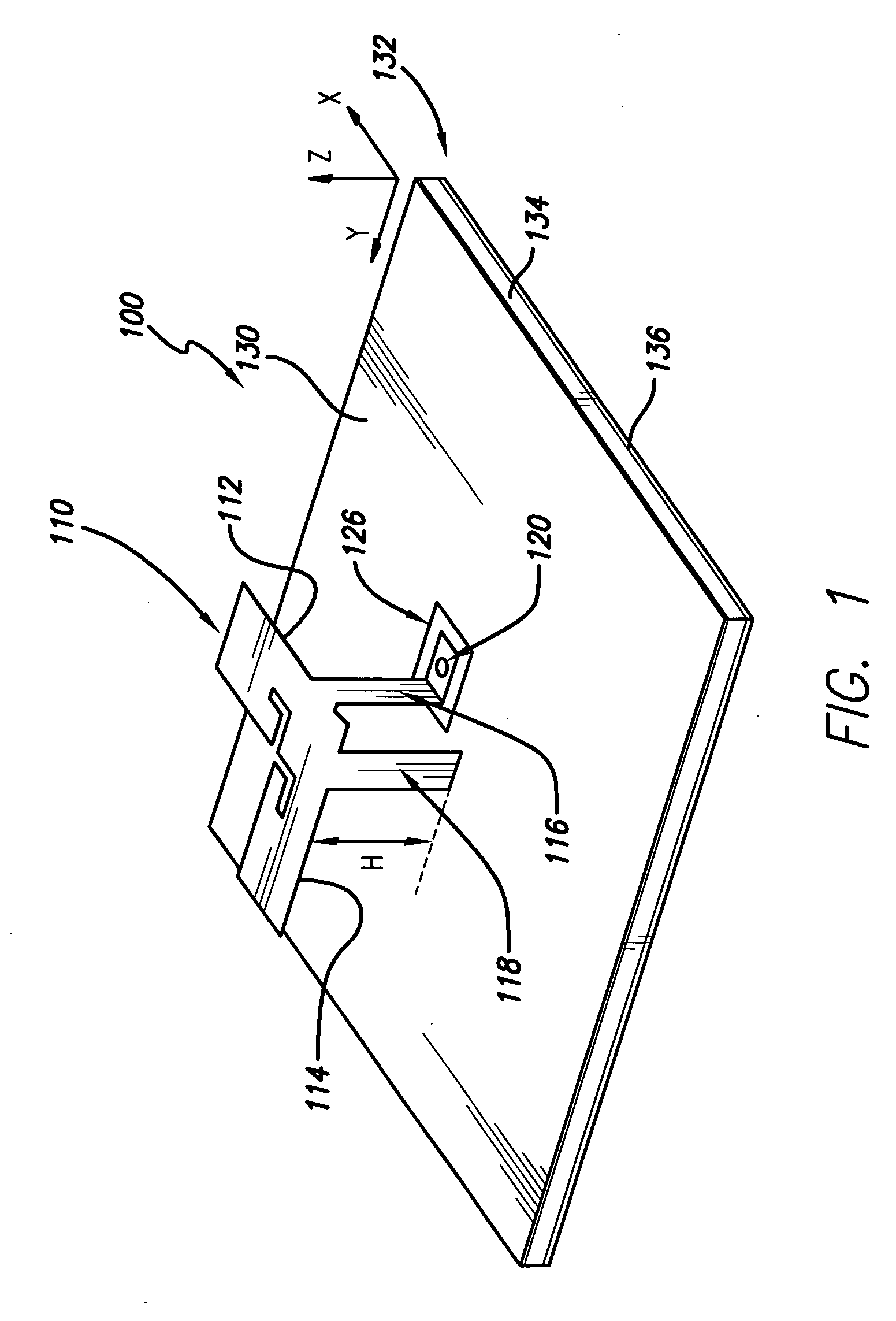
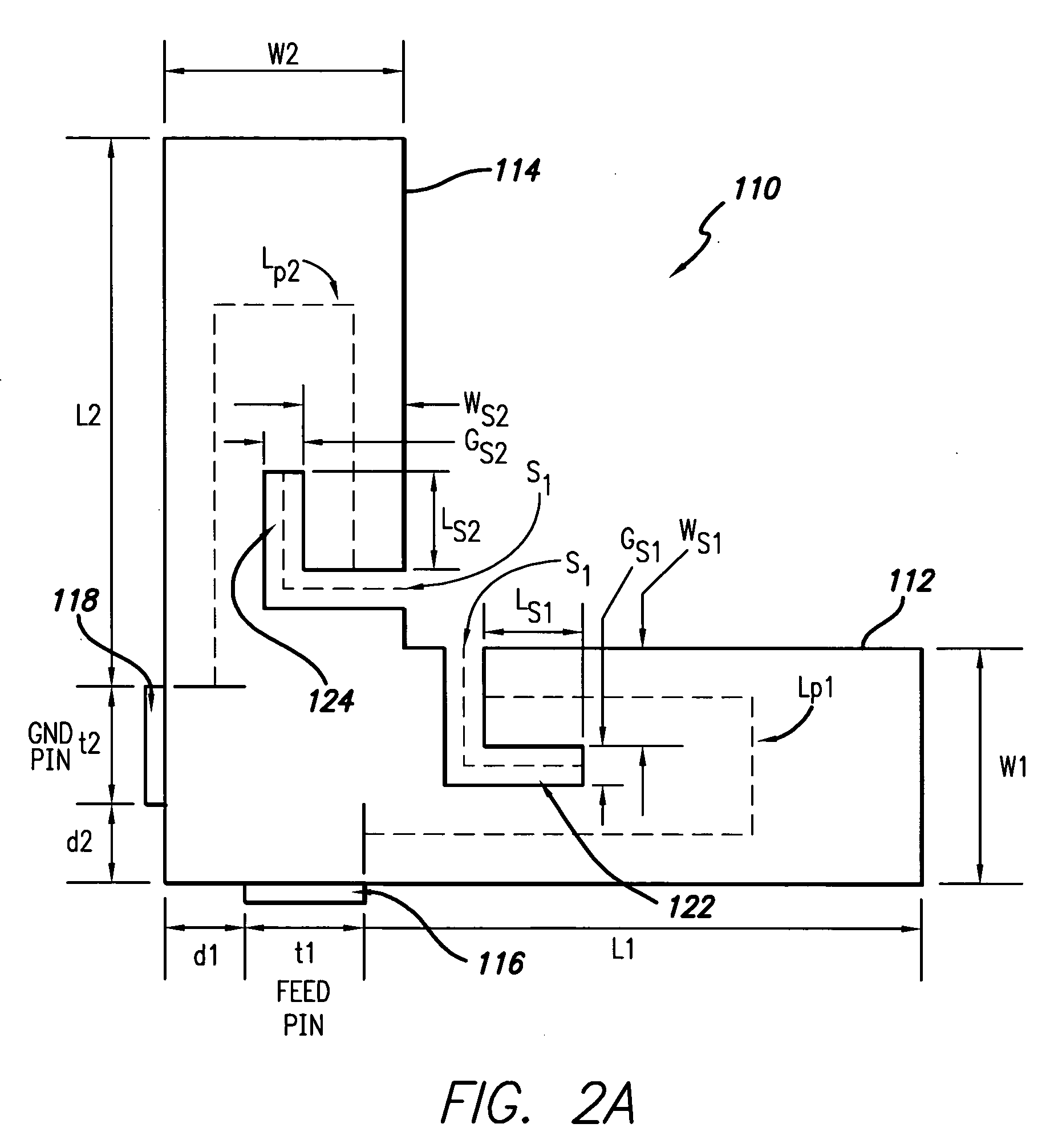
[0023]The mechanical structure of the preferred embodiment of the antenna 100 is illustrated in FIG. 1 and FIG. 2A, 2B. FIG. 1 shows a perspective view of the antenna illustrating the three dimensional structure while FIG. 2A and 2B show a top view illustrating the details of the antenna element layout over the ground plane. Also shown in FIG. 2A, 2B are specific dimensional parameters which may be varied to optimize antenna performance. One specific example of values of such parameters acc...


PUM


Abstract

A low cost and multi-featured antenna is disclosed. The antenna employs a radiating element mounted to a ground plane and having first and second branches spaced above the ground plane forming a generally L shaped planar radiating structure. The antenna can be either linear or circular polarization, and can be either single band or dual band, and only one feeding port is needed to obtain circular polarization. The antenna can be easily applied to various frequency bands.

Description

RELATED APPLICATION INFORMATION[0001]This application claims the benefit under 35 U.S.C. 119 (e) of U.S. provisional patent application Ser. No. 60 / 930,738, filed on May 18, 2007, the disclosure of which is incorporated herein by reference in its entirety.FIELD OF THE INVENTION[0002]The present invention relates to antennas for wireless communications systems. More particularly, the present invention relates to antennas for wireless cellular base stations.BACKGROUND OF THE INVENTION[0003]The number of base station antennas needed for cellular and other wireless communications applications is increasing rapidly due to increased use of mobile wireless communications. Therefore, it is desirable to design low cost base station antennas. At the same time such wireless applications increasingly will require wideband capability. Also some applications require that the antenna can be either linear or circular polarized.[0004]Increasingly, some practical applications also require that the an...

Claims


Application Information

Patent Timeline
Patent Type & Authority Applications(United States)
IPC IPC(8): H01Q9/04
CPCH01Q9/0421
Inventor HE, ZIMING
Owner INTEL CORP
Why Eureka
Try Eureka