Display device, control method and computer program for display device

a display device and control method technology, applied in the direction of instruments, color signal processing circuits, computing, etc., can solve the problems of deterioration of light emitting elements, and achieve the effect of reducing the speed of deterioration of self-light emitting elements and improving color temperatur

Active Publication Date: 2008-11-20
JOLED INC
View PDF12 Cites 30 Cited by
  • Summary
  • Abstract
  • Description
  • Claims
  • Application Information

AI Technical Summary

Benefits of technology

[0015]The coefficient calculating section may calculate coefficients for adjusting luminance of the other colors to the lowest luminance of a color as a result of acquiring the luminance information in the luminance acquiring section. According to this constitution, the coefficient calculating section calculates coefficients for adjusting the luminance of the other colors to the lowest luminance of the color as a result of acquiring the luminance information in the luminance acquiring section. As a result, since the luminance is reduced so that the luminance of the other colors is adjusted to the lowest luminance of that color and a video is displayed, a deteriorating speed of the self-light emitting elements can be slowed.
[0016]The light emission amount detecting section detects the amount of light emission in the plurality of regions on the screen, and the signal level correcting section may correct the amount of light emission according to a region where the luminance is the lowest. According to this constitution, the light emission amount detecting section detects the amount of light emission in the plurality of regions on the screen, and the signal level correcting section corrects the amount of light emission according to a region where the luminance is the lowest. As a result, the luminance on the entire screen is adjusted to the lowest luminance, the color temperature on the entire screen can be adjusted.
[0017]The light emission amount detecting section may move the plurality of regions on the screen up and down so as to detect the amount of light emission. According to this constitution, the light emission amount detecting section moves the plurality of regions on the screen up and down so as to detect the amount of light emission. As a result, the luminance on the screen can be detected uniformly, and the color temperature can be corrected more effectively.

Problems solved by technology

However, since the elements emit light by themselves in the self-light emitting display devices, the light emitting elements are deteriorated due to the continuous light emission.

Method used


Image

  • Display device, control method and computer program for display device
  • Display device, control method and computer program for display device
  • Display device, control method and computer program for display device

Examples


Embodiment Construction

[0040]Hereinafter, preferred embodiments of the present invention will be described in detail with reference to the appended drawings. Note that, in this specification and the appended drawings, structural elements that have substantially the same function and structure are denoted with the same reference numerals, and repeated explanation of these structural elements is omitted.

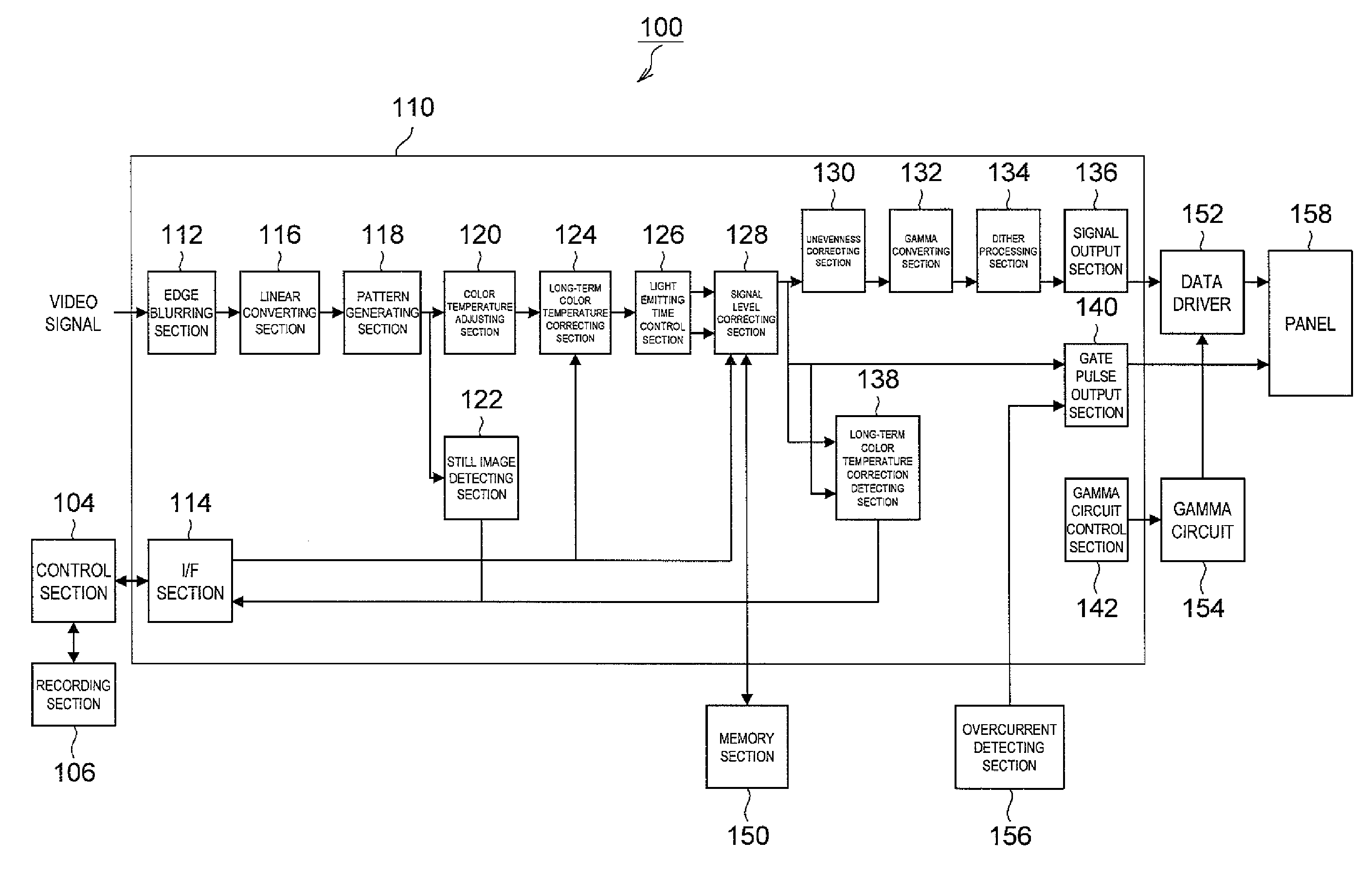
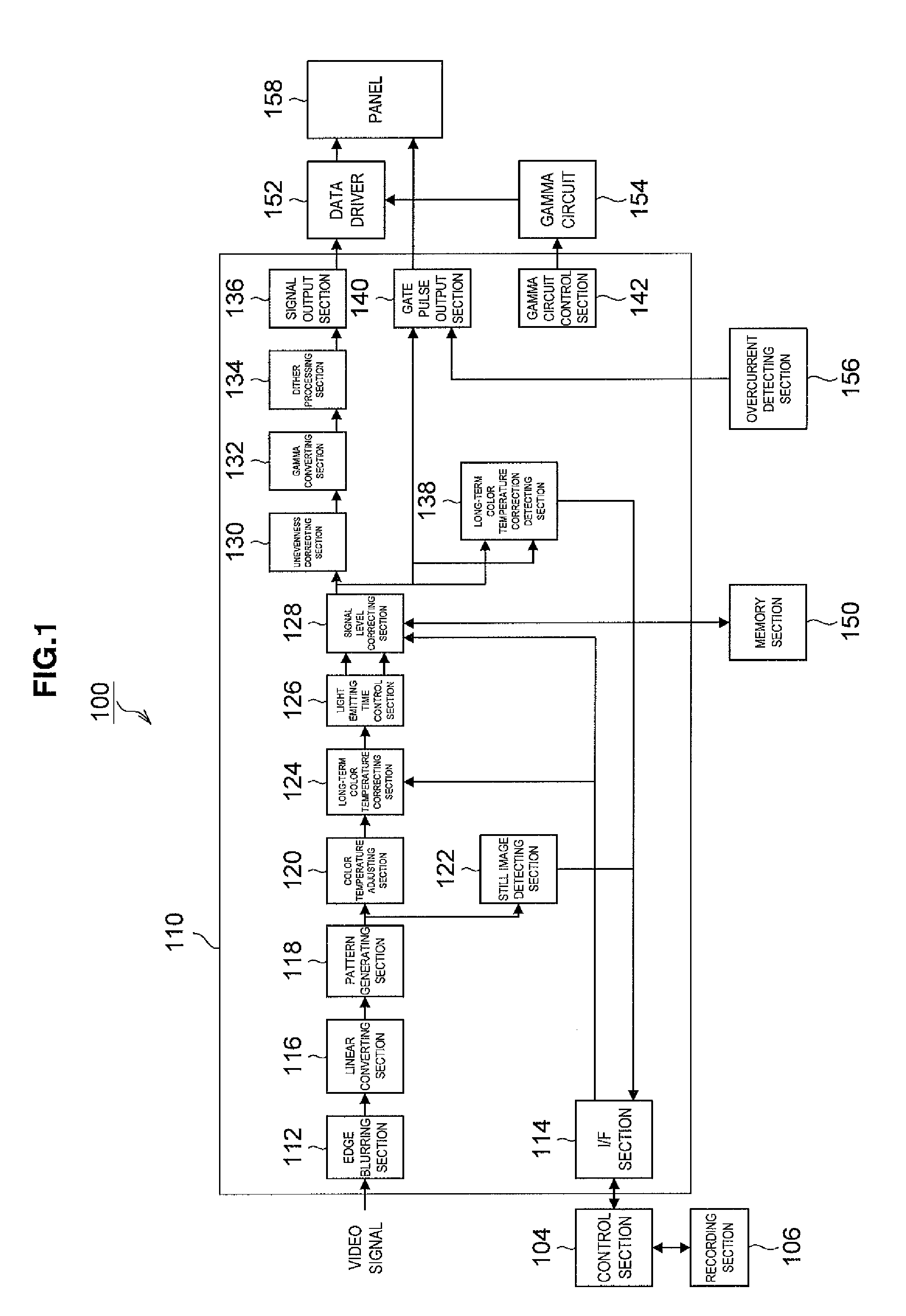
[0041]FIG. 1 is an explanatory diagram explaining a constitution of a display device 100 according to one embodiment of the present invention. The constitution of the display device 100 according to one embodiment of the present invention is described below with reference to FIG. 1.

[0042]As shown in FIG. 1, the display device 100 according to one embodiment of the present invention includes a control section 104, a recording section 106, a signal processing integrated circuit 110, a memory section 150, a data driver 152, a gamma circuit 154, an overcurrent detecting section 156 and a panel 158.

[0043]The sign...


PUM


Abstract

A display device includes: a light emission amount detecting section which inputs video signals having linear property and detects an amount of light emission from the video signals; a light emitting time calculating section which calculates light emitting time of the light emitting elements based on the amount of light emission detected by the light emission amount detecting section; a light emitting time recording section which records the calculated light emitting time; a luminance acquiring section which, acquires luminance information of the light emitting elements using the light emitting time recorded in the light emitting time recording section; a coefficient calculating section which calculates coefficients by which the video signals are multiplied based on the luminance information acquired by the luminance acquiring section; and a coefficient multiplying section which multiplies the video signals by the coefficients calculated by the coefficient calculating section.

Description

CROSS-REFERENCE TO RELATED APPLICATION[0001]The present invention contains subject matter related to Japanese Patent Application JP 2007-133229 filed in the Japan Patent Office on May 18, 2007, the entire contents of which being incorporated herein by reference.BACKGROUND OF THE INVENTION[0002]1. Field of the Invention[0003]The present invention relates to a display device and a control method for display device. More specifically, the invention relates to the active matrix type display device where scanning lines for selecting pixels in a predetermined scanning cycle, data lines for giving luminance information for driving the pixels, and pixel circuits for controlling a current amount based on the luminance information and allowing light emitting elements to emit light according to the current amount are arranged into a matrix pattern, and the control method for the display device.[0004]2. Description of the Related Art[0005]As flat and thin display devices, liquid crystal display...

Claims


Application Information

Patent Timeline
Patent Type & Authority Applications(United States)
IPC IPC(8): G06F3/038
CPCG09G3/3225G09G2310/0232G09G2320/045G09G2320/048G09G2320/0666H04N9/73G09G2320/103G09G2340/0442G09G2340/16G09G2360/145G09G2360/16G09G2320/0673H10K59/351
Inventor MORI, HIDETOKIKUCHI, KENINOUE, YASUOMEGURO, TAKEYASHIDARA, HIDEHIKOITO, MASAHIROOSUMI, TOYO
Owner JOLED INC
Why Eureka
Try Eureka