
Method for Making an Optical Fiber Comprising Nanoparticles and Preform Used in the Manufacture of Such a Fiber

Active Publication Date: 2008-11-20
RPX CORP
View PDF9 Cites 7 Cited by
  • Summary
  • Abstract
  • Description
  • Claims
  • Application Information

AI Technical Summary

Benefits of technology

[0011]The preform is made into fibers by introducing a non-oxidizing gas into the recess, thereby limiting the chances that the nanoparticles in the preform will oxidize.
[0017]In this manner, a method using a preform in a manner consistent with the invention makes it possible to preserve the nanoparticles arranged in this preform, and keep them within a non-oxidizing environment during the preform's fiber-forming step. This environment is generated by a gas found in their vicinity, which heavily limits their oxidization and eliminates, or at least reduces, the alteration of nanoparticles in the core of the fiber.
[0018]Furthermore, a larger variety of nanoparticles may be implemented in manufacturing optical fibers, given that the environment to which these nanoparticles are subjected during the preform's fiber-forming step is less hostile. For this reason, it is possible to develop the usage of new fibers.
[0019]In one embodiment, the preform comprises a longitudinal axis and the recess is coaxial to said preform axis, which facilitates the flow of the reducing gas during the fiber-forming step across the entire length of the preform.
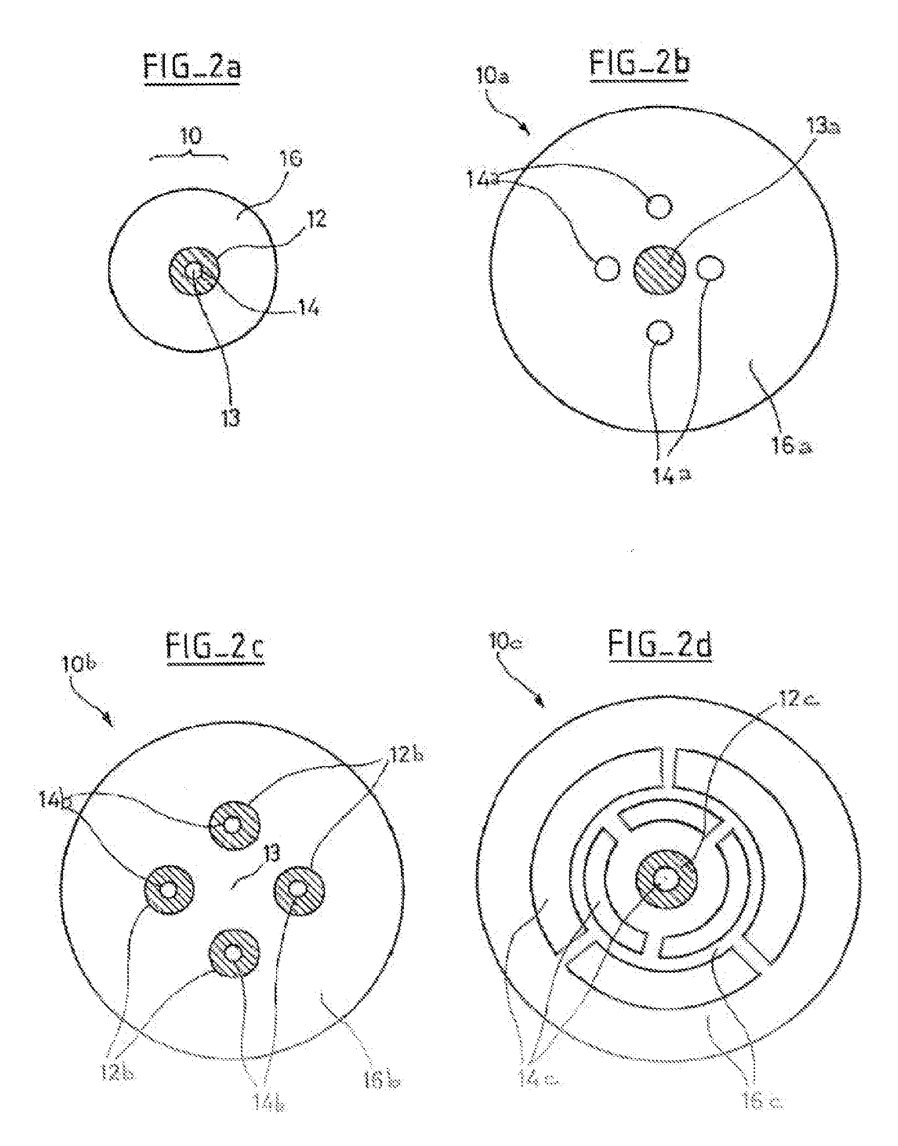
[0020]In one embodiment, the preform comprises a plurality of recesses that are coaxial to the preform's axis, which makes it possible to bring a non-oxidizing gas into the vicinity of a plurality of doped zones in the preform, among other possibilities.
[0021]In one embodiment, the preform comprises a plurality of recesses that form circles and / or arcs of circles that are concentric with respect to the axis of the preform, said embodiment allowing the preform to be manufactured in a simple manner.

Problems solved by technology

However, hear treatment is performed with temperatures greater than 500° C., and usually greater than 1000° C. These high temperatures lead to alterations in the composition and / or structure of these nanoparticles, and therefore in their properties.

Method used


Image

  • Method for Making an Optical Fiber Comprising Nanoparticles and Preform Used in the Manufacture of Such a Fiber
  • Method for Making an Optical Fiber Comprising Nanoparticles and Preform Used in the Manufacture of Such a Fiber
  • Method for Making an Optical Fiber Comprising Nanoparticles and Preform Used in the Manufacture of Such a Fiber

Examples


Embodiment Construction

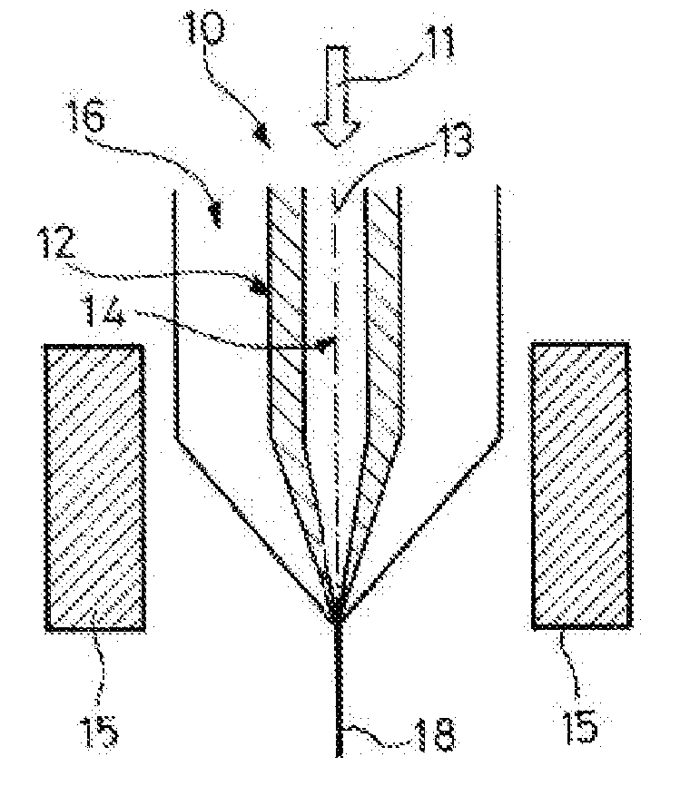
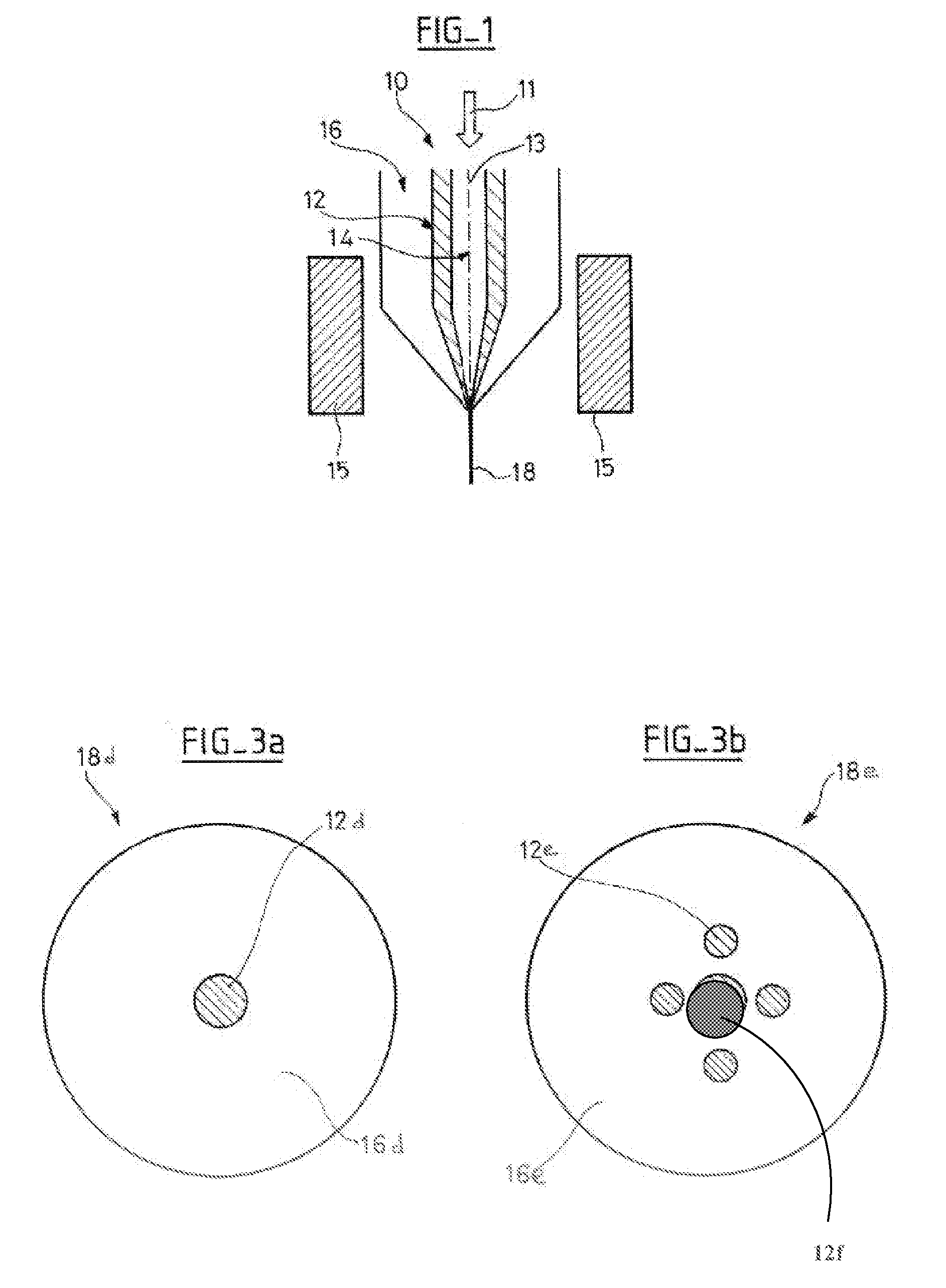
[0028]FIG. 1 depicts the obtaining of an optical fiber 18 via a method for forming fiber from a preform 10 in accordance with the invention, meaning that a non-oxidizing gas 11, such as a reducing gas, is kept in the vicinity of the doped zone 12 of the preform 10 by flowing into a recess 14 that is coaxial to the axis 13 of the preform 10.

[0029]In this manner, the nanoparticles included in the doped zone 12 of the material 16 of the preform 10 are protected from oxidization by the presence of this non-oxidizing gas 11 during the step in which fiber is formed from the preform 10, which is conducted using devices 15 that heat said preform.

[0030]By these means, the alteration of the composition and / or structure of the nanoparticles present in the doped areas 12 is heavily limited. In other words, the conditions to which the nanoparticles are subjected are less hostile, so that nanoparticles with various compositions can be used in the preform 10, and consequently, in the fiber 18 obta...


PUM

PropertyMeasurementUnit
Temperatureaaaaaaaaaa

Abstract

The invention concerns a method for making an optical fiber (18) including the following steps: producing a preform (10) containing nanoparticles provided with an active element including at least one recess (14) proximate at least part of the nanoparticles; fiber drawing of the preform (10) by introducing a non-oxidizing gas in the recess (14), thereby limiting the risks of oxidizing the nanoparticles of the preform (10). The preform (10) designed to the manufacture of an optical fiber (18) by the inventive method comprises nanoparticles provided with an active element in a doped zone (12) and at least one recess (14) proximate the doped zone (12).

Description

FIELD OF THE INVENTION[0001]The present invention concerns a preform intended for manufacturing an optical fiber, as well as a method for manufacturing an optical fiber implementing such a preform.PRIOR ART[0002]In the field of telecommunications, it is known in the art how to use planar guides or optical fibers to transmit optical signals, by simultaneously processing these signals.[0003]For example, an optical fiber may amplify the optical signal transmitted. To do so, such an amplifying fiber comprises a core, made up of a transparent material, and an active element, or doping agent, generally made from rare earth materials such as Er-ions, intended to amplify the intensity of the optical signal transmitted, and a cladding surrounding the core, intended to keep the majority of the optical signal within the core of the fiber.[0004]The use of such an optical fiber may be improved by implementing nanoparticles within the core of the fiber, said nanoparticles comprising the active el...

Claims


Application Information

Patent Timeline
IPC IPC(8): G02B6/02C03B37/018B32B5/16
CPCB82Y20/00Y10T428/25C03B2201/06C03B2201/34C03B2205/12C03C13/04C03C14/006C03C2214/16G02B6/0229G02B6/02366G02B6/02371H01S3/06729H01S3/06737H01S3/06741H01S3/169C03B37/02754
Inventor GASCA, LAURENTBLANCHANDIN, STEPHANIEPASTOURET, ALAINSIMONNEAU, CHRISTIAN
Owner RPX CORP
Learn More