
Method and system for controlling compaction machines

Inactive Publication Date: 2008-11-20
BOMAG
View PDF0 Cites 8 Cited by
  • Summary
  • Abstract
  • Description
  • Claims
  • Application Information

AI Technical Summary

Benefits of technology

[0010]This means that the compaction machine can be operated with very high efficiency concerning compaction effect and degree of compaction. At the same time, the surrounding structures and especially those susceptible to oscillations can be protected in the best possible way against vibrations, such that they are subjected to oscillations to an extent not more than is permissible.

Problems solved by technology

A relevant problem in this respect is that the compaction machine per se as well as structures in the surrounding area can be damaged by the oscillations.
This is especially problematic in cases where the frequency of the oscillation excitation lies in the range of the local natural frequency of the machine or the ground, or when large oscillation amplitudes are applied.

Method used


Image

  • Method and system for controlling compaction machines
  • Method and system for controlling compaction machines
  • Method and system for controlling compaction machines

Examples


Embodiment Construction

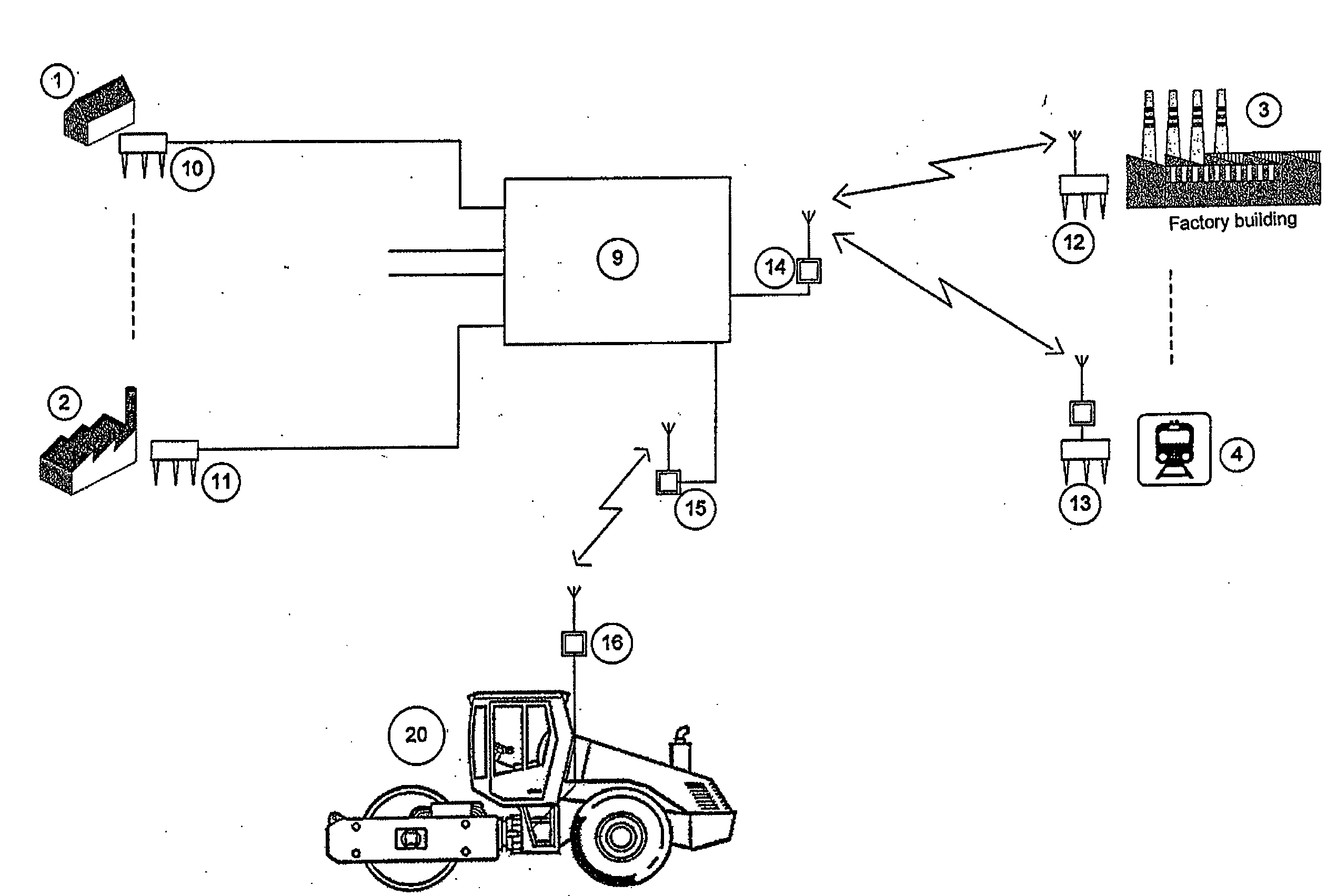
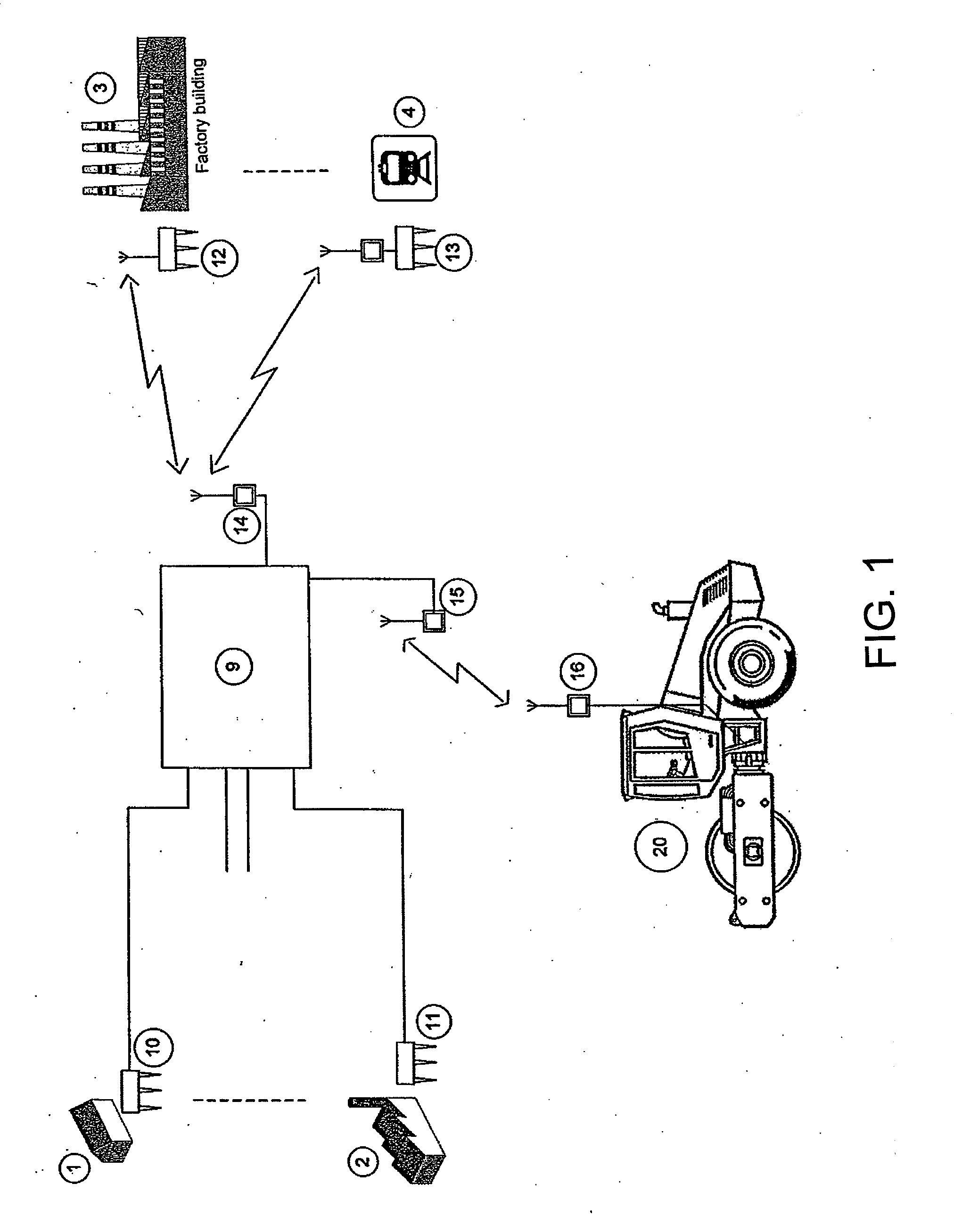
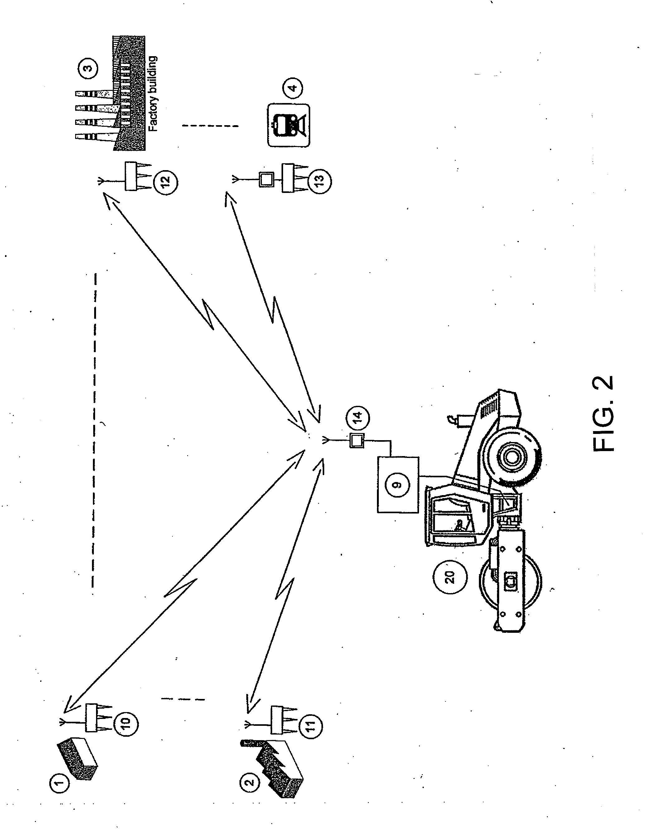
[0018]The embodiment according to FIG. 1 comprises a compaction machine 20 which is arranged as a roller machine. It is preferably used in earthwork and asphalt construction for compaction of the ground. It can naturally also concern a plate compactor or another configuration. The compaction machine 20 is controlled by a data-processing unit 9. Several sensor or building sensors are arranged in the area of the construction site for detecting oscillations or vibrations on the building structures. Sensor 10 is arranged on a residential building 1 and sensor 11 on a factory building 2. Both sensors 10 and 11 send the detected measured oscillation values to the data processing unit 9 which is arranged in this case simultaneously as a data acquisition unit. Data transmission occurs via a cable connection. Furthermore, a sensor 12 is arranged in a factory building 3 and a sensor 13 in the area of a train tunnel 4. The train tunnel stands as an example for other comparable structures such ...


PUM


Abstract

A method and a system is described for controlling at least one compaction machine in which the oscillations propagating from the compaction machine in the ground are detected by means of a sensor at least at one relevant measuring location. The measured oscillation values as detected by the sensor are sent to a data-processing unit which then compares the same with a permissible oscillation limit value for the respective measuring location. Upon exceeding the limit value, at least one compaction parameter of the compaction machine is changed in such a way that the measured oscillation values as measured at the measuring location are set by a control loop circuit automatically to a value smaller than or equal to the oscillation limit value.

Description

FIELD OF THE INVENTION[0001]The invention relates to a method for controlling a compaction machine for the purpose of automatic adjustment of compaction parameters of said compaction machines and relates especially to a respective system for controlling such a compaction machine.BACKGROUND OF THE INVENTION[0002]Compaction machines or devices of the respective kind are used for compacting soil, grounds, traffic routes, dams and the like. Such compaction machines are known in different embodiments from the state of the art. These can concern for example, but not exclusively, automotive rollers or towed rollers. The invention must be distinguished from apparatuses (such as rams or beetle heads) for driving land ties and the like into the ground.[0003]In order to improve the compaction effect and for increasing the degree of compaction, a vibration superimposition or oscillation excitation of the compaction tools is known, for which reference is made in lieu to DE 33 08 476 A1. The resp...

Claims


Application Information

Patent Timeline
IPC IPC(8): E01C23/07
CPCE01C19/288G06Q50/08E02D3/026
Inventor LAUX, ROBERT
Owner BOMAG
Learn More