
Double-headed piston type compressor

Inactive Publication Date: 2008-11-20
TOYOTA IND CORP
View PDF10 Cites 12 Cited by
  • Summary
  • Abstract
  • Description
  • Claims
  • Application Information

AI Technical Summary

Benefits of technology

[0005]Accordingly, it is an objective of the present invention to provide a double-headed piston type compressor having a rotary valve, capable of suppressing the occurrence of a resonant phenomenon in an external device due to pulsations caused when refrigerant is drawn into each of the compression chambers and thereupon controlling noise.

Problems solved by technology

The pulsations resonate an external device such as the piping or the external refrigerant circuit, whereupon noise can be caused in a passenger compartment.

Method used


Image

  • Double-headed piston type compressor
  • Double-headed piston type compressor
  • Double-headed piston type compressor

Examples


first embodiment

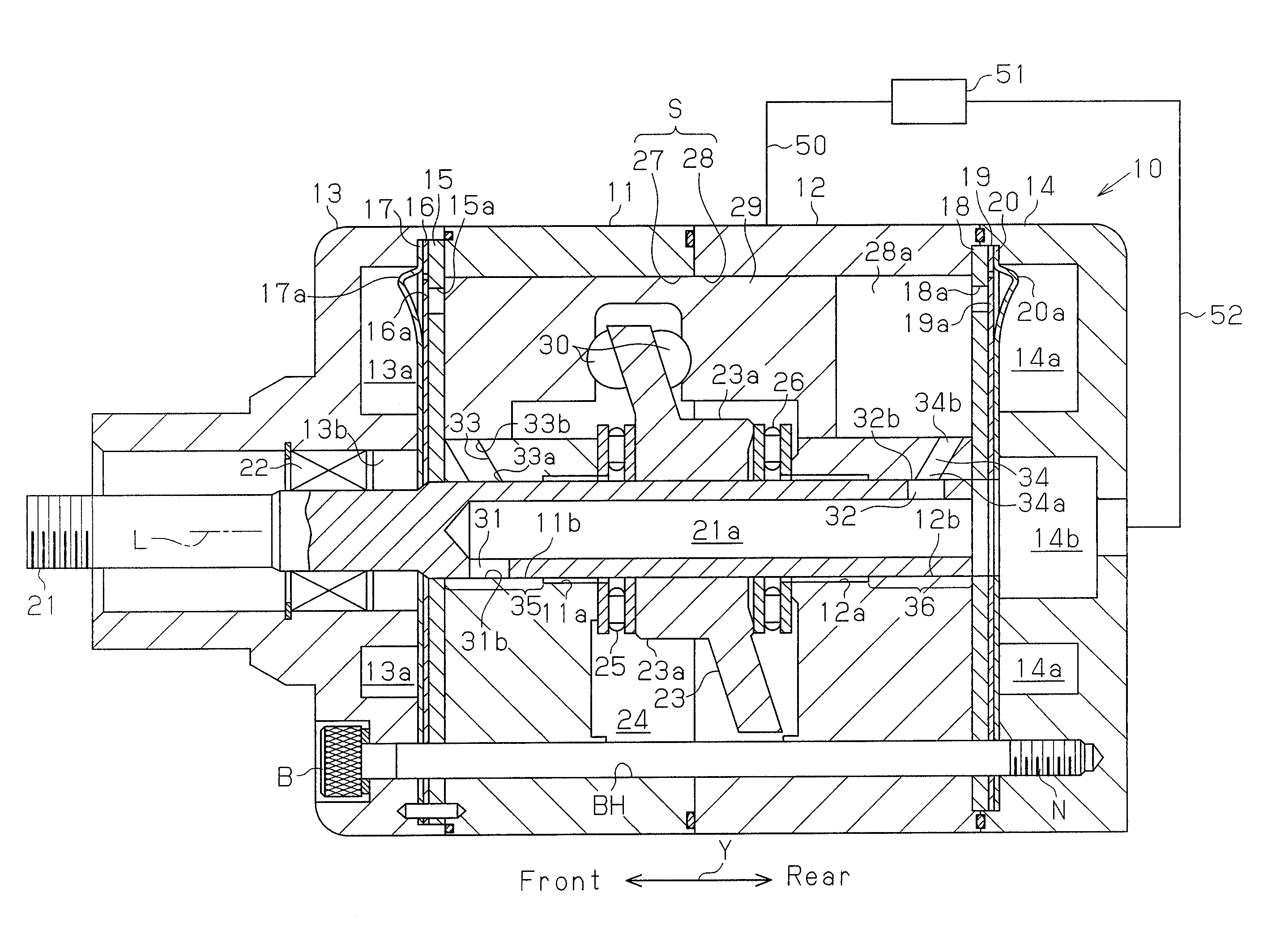
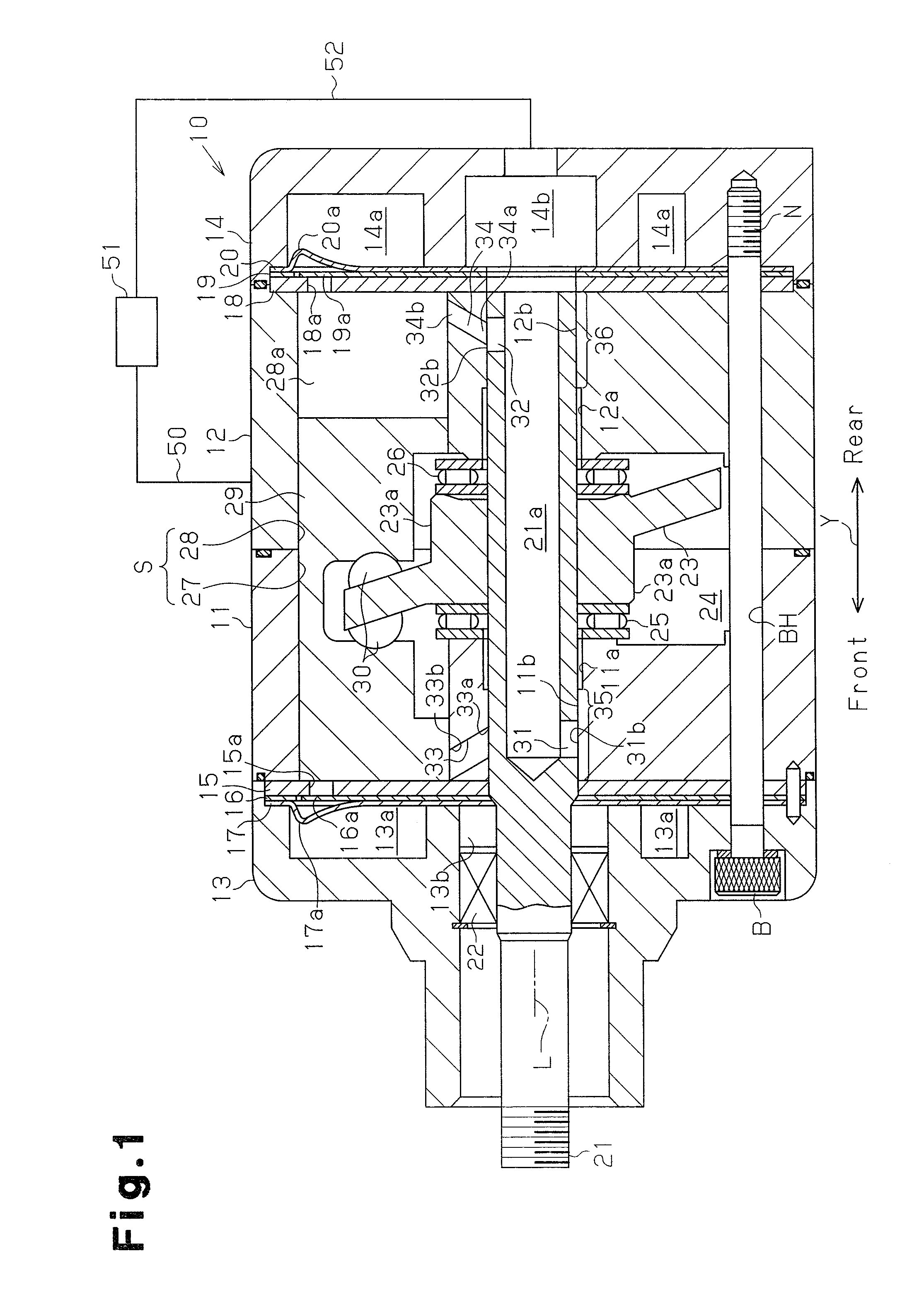
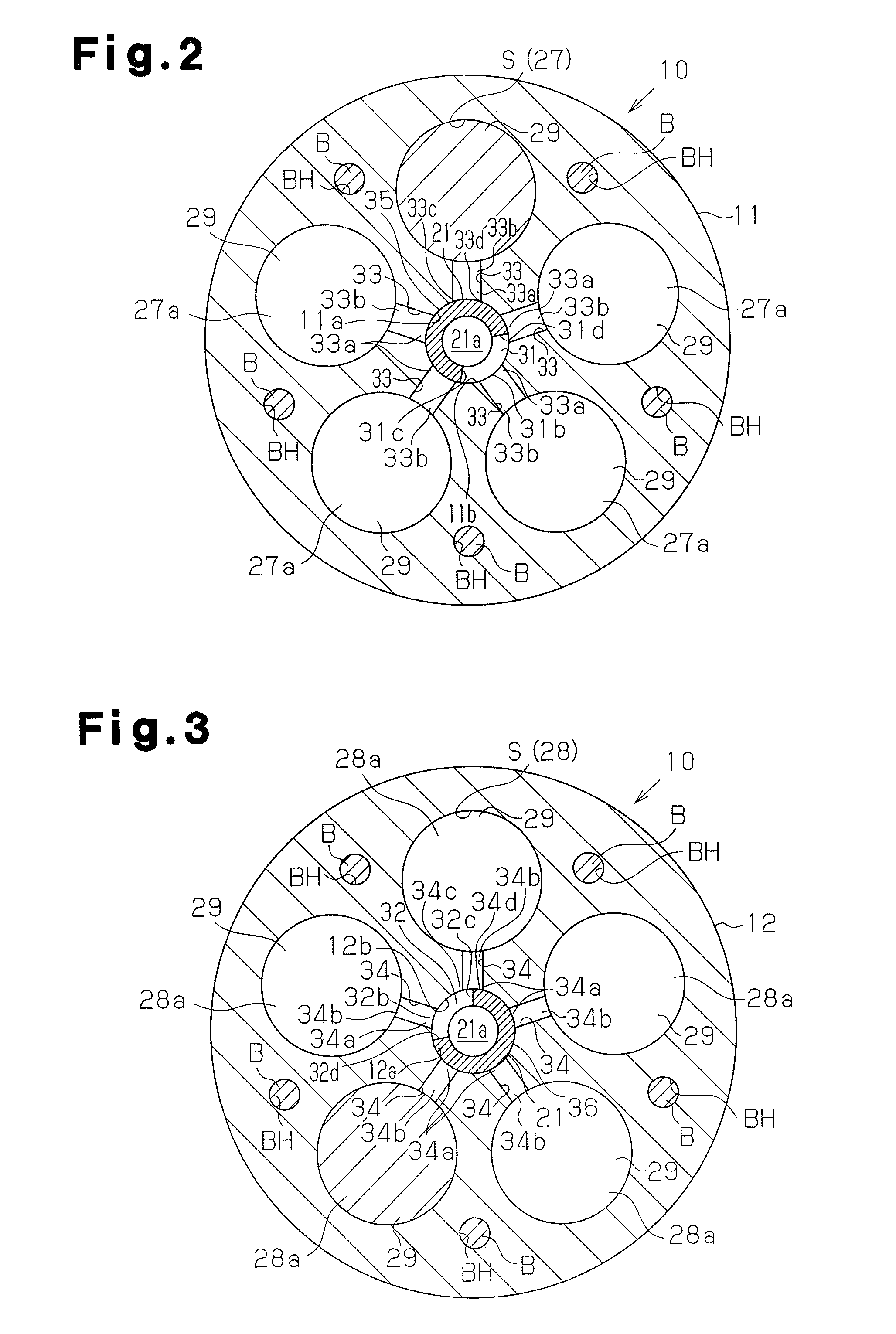
[0048]In the first embodiment, the angle θ1 of the rotary shaft 21 is designed to be smaller than the angle θ2. Therefore, when the rotary shaft 21 rotates 180 degrees from when the inlet 33a of the first suction passage 33 is in a state of the communication start timing in the first rotary valve 35, the inlet 34a of the second suction passage 34 is not in a state of the communication start timing but is in a state prior to the communication start timing. The difference between the angle θ1 and the angle θ2 is preferably set to 2 to 15 degrees. When the difference is smaller than 2 degrees, there can be unfavorably a case where the difference in angle is not generated due to manufacturing errors of the first introduction passage 31 and the second introduction passage 32. On the other hand, when the difference is greater than 15 degrees, the communication start timing in the second compression chamber 28a is delayed drastically so that a suction amount of the refrigerant into the sec...

second embodiment

[0067]The angle θ1 of the rotary shaft 21 rotating from the top dead center timing in the first compression chamber 27a to the communication start timing is smaller than the angle θ2 of the rotary shaft 21 rotating from the top dead center timing in the second compression chamber 28a to the communication start timing. In the second embodiment, the time period from when the double-headed piston 29 reaches the top dead center in the first compression chamber 27a to when the first introduction passage 31 and the first suction passage 33 start to communicate with each other can be made longer than the time period from when the double-headed piston 29 reaches the top dead center in the second compression chamber 28a to when the second introduction passage 32 and the second suction passage 34 start to communicate with each other.

[0068]Therefore, according to the second embodiment, an advantage below is obtained in addition to the same advantages (1) to (4) in the first embodiment.

[0069](5...


PUM


Abstract

A double-headed piston type compressor connected with an external device is provided. The compressor includes a plurality of cylinder bore pairs, double-headed pistons, a first rotary valve, a second rotary valve, first suction passages, and second suction passages. In each cylinder bore pair, a first time period from a first top dead center timing, which is timing when the double-headed piston reaches a top dead center in a first compression chamber, to a first communication start timing, which is timing when a first introduction passage starts to communicate with a first suction passage, is different from a second time period from a second top dead center timing, which is timing when the double-headed piston reaches a top dead center in a second compression chamber, to a second communication start timing, which is timing when the second introduction passage starts to communicate with a second suction passages.

Description

BACKGROUND OF THE INVENTION[0001]The present invention relates to a double-headed piston type compressor provided with rotary valves on both ends of a rotary shaft.[0002]As a vehicle air-conditioning compressor, a double-headed piston type compressor has been in use, for example. In the compressor of this kind, each of a plurality of double-headed pistons is housed in a pair of front and rear cylinder bores. A housing of the compressor has a swash plate chamber for accommodating a swash plate which rotates with a rotary shaft. Rotation of the swash plate reciprocates the double-headed pistons within the cylinder bores. The double-headed piston defines a compression chambers in the cylinder bore. Along with the reciprocation, the double-headed piston draws refrigerant into the compression chambers via a refrigerant suction system. The double-headed piston also compresses the refrigerant in the compression chambers and then discharges the refrigerant to discharge chambers.[0003]The re...

Claims


Application Information

Patent Timeline
IPC IPC(8): F04B27/10F04B39/10
CPCF04B27/1018F04B39/10F04B39/0027F04B27/08F04B39/00
Inventor SUGIURA, MANABUSAIKI, AKIODETO, NORIKAZUHOTTA, KAZUHIRO
Owner TOYOTA IND CORP
Features
  • Generate Ideas
  • Intellectual Property
  • Life Sciences
  • Materials
  • Tech Scout
  • Unparalleled Data Quality
  • Higher Quality Content
  • 60% Fewer Hallucinations
Learn More