Determining destinations of a dynamic branch

a dynamic branch and destination technology, applied in the direction of program control, next instruction address formation, instruments, etc., can solve the problems of increasing complexity of tasks, increasing translation difficulty, and exacerbated problems

Inactive Publication Date: 2008-11-20
KRABLIN G LAWRENCE +3
View PDF15 Cites 8 Cited by
  • Summary
  • Abstract
  • Description
  • Claims
  • Application Information

AI Technical Summary

Benefits of technology

[0008]The plurality of basic blocks in the first code state of the programming code are identified, as are links between the identified basic blocks. A control flow graph / representation (CFG) of the programming code is then constructed based on the identified basic blocks and identified links, where the CFG is in a preliminary form. At least one basic block ending in a dynamic branch is identified, and all identified basic blocks that lead to the dynamic branch are explored, based on the CFG, as far back as is necessary to fully determine a set of destination addresses for the dynamic branch.

Problems solved by technology

However, a problem arises in the situation where the machine code in the first state includes branch or destination address information, where such branch address information would be different for the machine code in the second state, and where explicit address information from the original compiler is absent.
The problem is exacerbated when branch address information does not translate in a fairly direct manner.
For a dynamic branch, however, the task becomes more complex.
Dynamic branches rely, in whole or in part, on results of calculations made prior to the branch, and thus present a more difficult problem for translation.

Method used


Image

  • Determining destinations of a dynamic branch
  • Determining destinations of a dynamic branch
  • Determining destinations of a dynamic branch

Examples


example

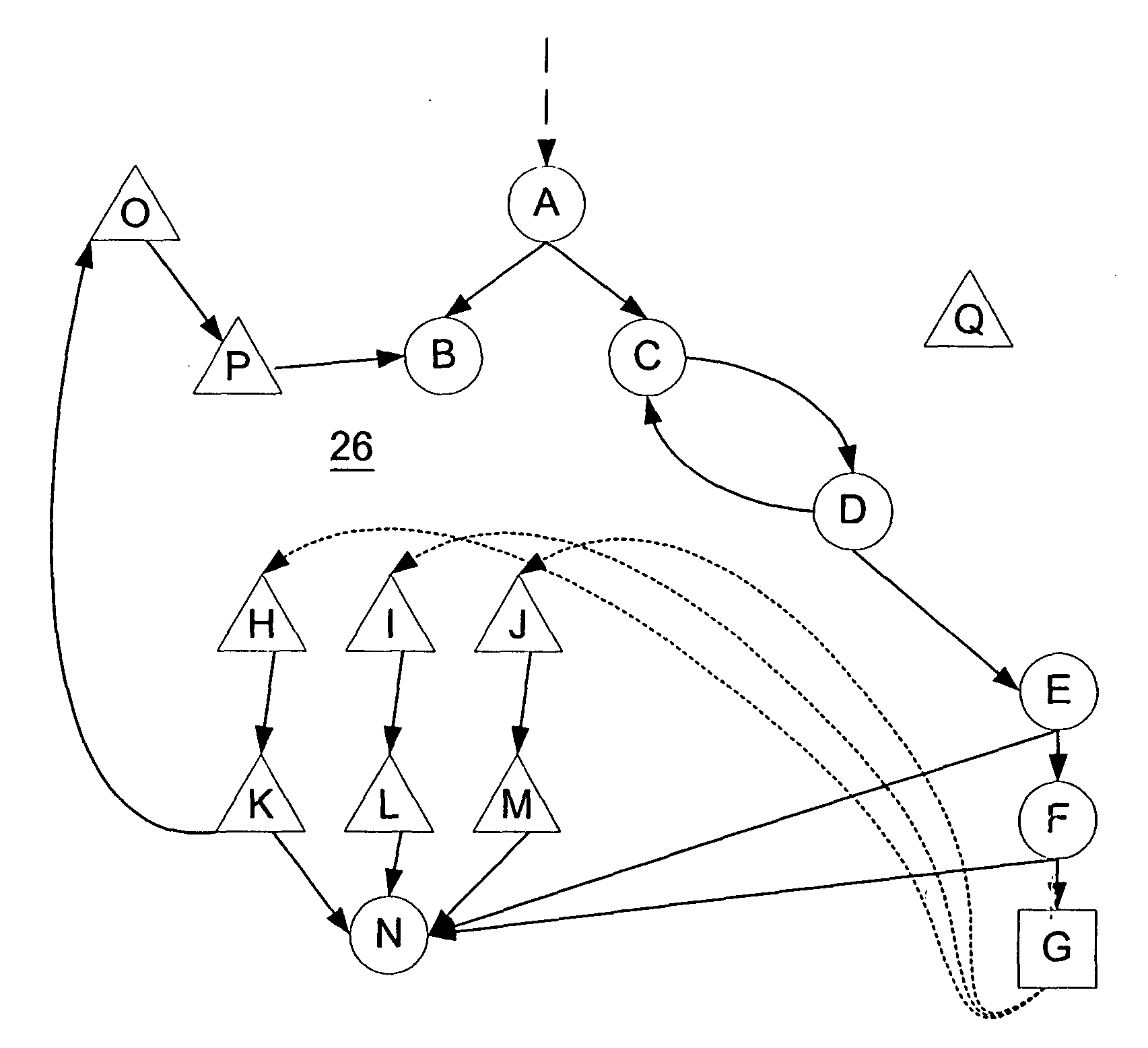
[0097]Assume the following three blocks 24 flow sequentially in a program 20, where the last block 24 ends in a dynamic branch:

Block 1:

[0098]

VALC A(get value of a variable A and place on stack)DUPL(duplicate value on top of stack and place on stack)LT 0(place value 0 on stack)LESS(consume top two values on stack and compare todetermine (in effect if A is less than zero), placecomparison result on stack)BRTR(consume top of stack and branch based thereon or elsefall through)

Block 2:

[0099]

DUPLLT 10GRTR(consume top two values on stack and compare to determine(in effect if A is greater than ten), place comparisonresult on stack)BRTR

Block 3:

[0100]

LT 50(place pre-defined offset value 50 on the stack)ADD(consume top two values on stack and add, place resulton stack)DBUN(consume top of stack and employ as address for dynamicbranch)

Accordingly, in block 1, the value A is tested to see if it is out of bounds at the lower end (i.e., less than zero), and in block 2, the value A is tested to s...


PUM


Abstract

A method, a translator, and a computer-readable medium for translating compiled programming code from a first code state to a second code state are disclosed. The programming code in the first state has a plurality of basic blocks, where each basic block has a set of instructions. At least one basic block ends in a dynamic branch, the dynamic branch being a transfer to one of a set of destinations based on a calculation of a destination address. The plurality of basic blocks in the first state of the programming code are identified, as are links between the identified basic blocks. A control flow graph (CFG) of the programming code is then constructed based on the identified basic blocks and identified links, where the CFG is in a preliminary form. At least one basic block ending in a dynamic branch is identified, and all identified basic blocks that lead to the dynamic branch are explored, based on the CFG, as far back as is necessary to fully determine a set of destination addresses for the dynamic branch. The set of destination addresses defines the set of destinations from the dynamic branch. Such set of destinations is examined to identify a branch table, and the CFG is updated to reflect the set of destinations and the identified branch table. The programming code is then translated from the first state to the second state based at least in part on the updated CFG.

Description

FIELD OF THE INVENTION[0001]The present invention relates to determining destinations of a dynamic branch in compiled computer code (i.e., machine code). More particularly, the present invention relates to determining every possible destination of such a dynamic branch so that the control flow of such computer code with respect to such dynamic branch may be accurately determined.BACKGROUND OF THE INVENTION[0002]In certain circumstances, it is useful to translate compiled machine code from a first state corresponding to a first instruction set to a second state corresponding to a second instruction set. As is known, such translating is preferable to the alternative: locating the source code from which the machine code in the first code state was derived; and writing and debugging a compiler to compile such located source code directly into the machine code in the second code state.[0003]As is also known, such translating from the first code state to the second code state is performed...

Claims


Application Information

Patent Timeline
Patent Type & Authority Applications(United States)
IPC IPC(8): G06F9/44G06F9/45G06F9/32
CPCG06F8/433G06F8/443G06F8/4451G06F8/52
Inventor KRABLIN, G. LAWRENCEJENNINGS, ANDREW T.FENDER, TIMOTHY N.STRATTON, WILLIAM
Owner KRABLIN G LAWRENCE
Why Eureka
Try Eureka