Fuel injector needle housing

a fuel injector and needle housing technology, applied in the field of internal combustion engines, can solve the problems of affecting the quality and efficiency of combustion, affecting the design of known fuel injectors as to the injection pressure of various components of fuel injectors, and known injectors exposed to higher injection pressures in laboratory and/or simulation settings

Inactive Publication Date: 2008-11-27
INT ENGINE INTPROP CO LLC
View PDF6 Cites 11 Cited by
  • Summary
  • Abstract
  • Description
  • Claims
  • Application Information

AI Technical Summary

Benefits of technology

[0006]A fuel injector for injecting fuel into a cylinder of an internal combustion engine includes an injector body and a needle valve. A feed passage fluidly connects a needle chamber with a source of high pressure fuel. The needle chamber is formed in a needle housing and has a centerline extending along its length. The needle valve is located in the needle chamber. A collection cavity is formed in the needle housing and in fluid communication with the needle chamber. The collection cavity is positioned between the needle chamber and the feed passage. The collection cavity is advantageously symmetrical about a plane that is perpendicular to the centerline of the needle chamber.

Problems solved by technology

Fuel vaporization, especially in compression ignition engines, directly affects the quality and efficiency of combustion.
Known fuel injector designs have limitations as to the injection pressure various components of the fuel injector can tolerate.
Known injectors exposed to higher injection pressures in a laboratory and / or simulation setting has experienced failures.

Method used


Image

  • Fuel injector needle housing
  • Fuel injector needle housing
  • Fuel injector needle housing

Examples


Embodiment Construction

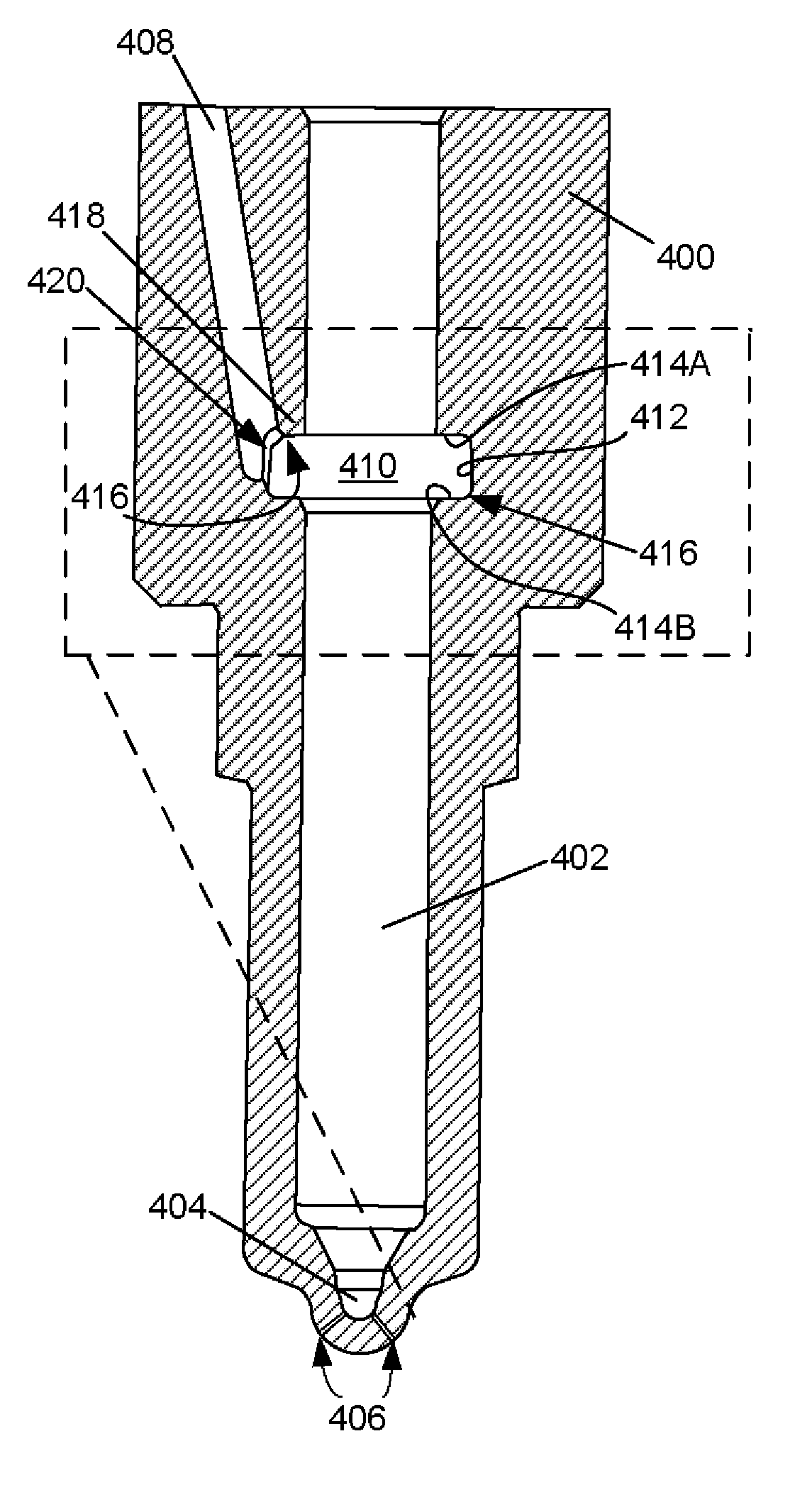
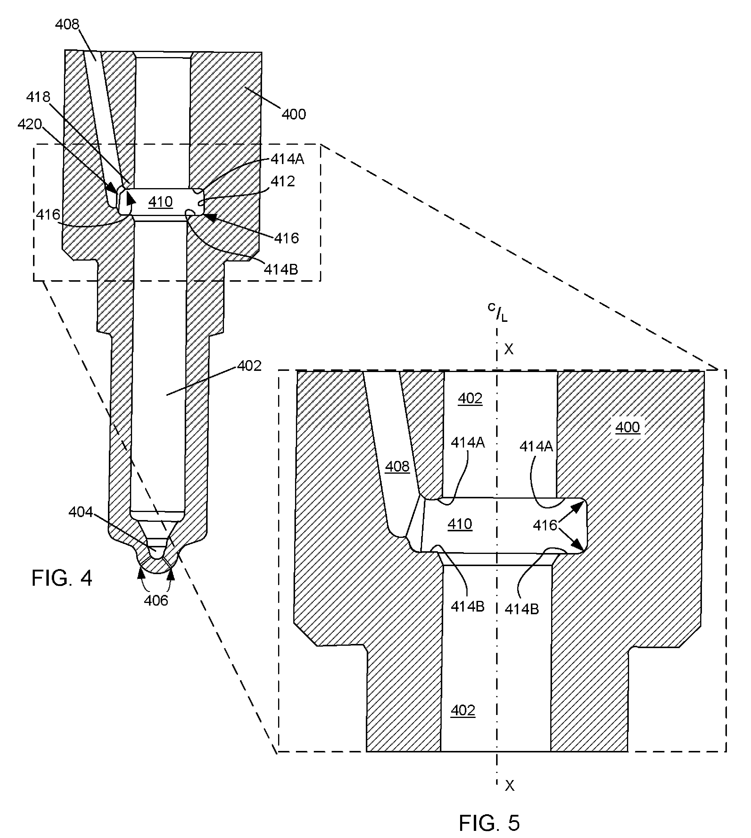
[0011]The following describes an apparatus for enabling operation of a fuel injector at higher pressure levels than was previously possible. The embodiments described herein are alternative designs for a needle housing of a fuel injector that advantageously require a minimum degree of changes to other components of the fuel injector.

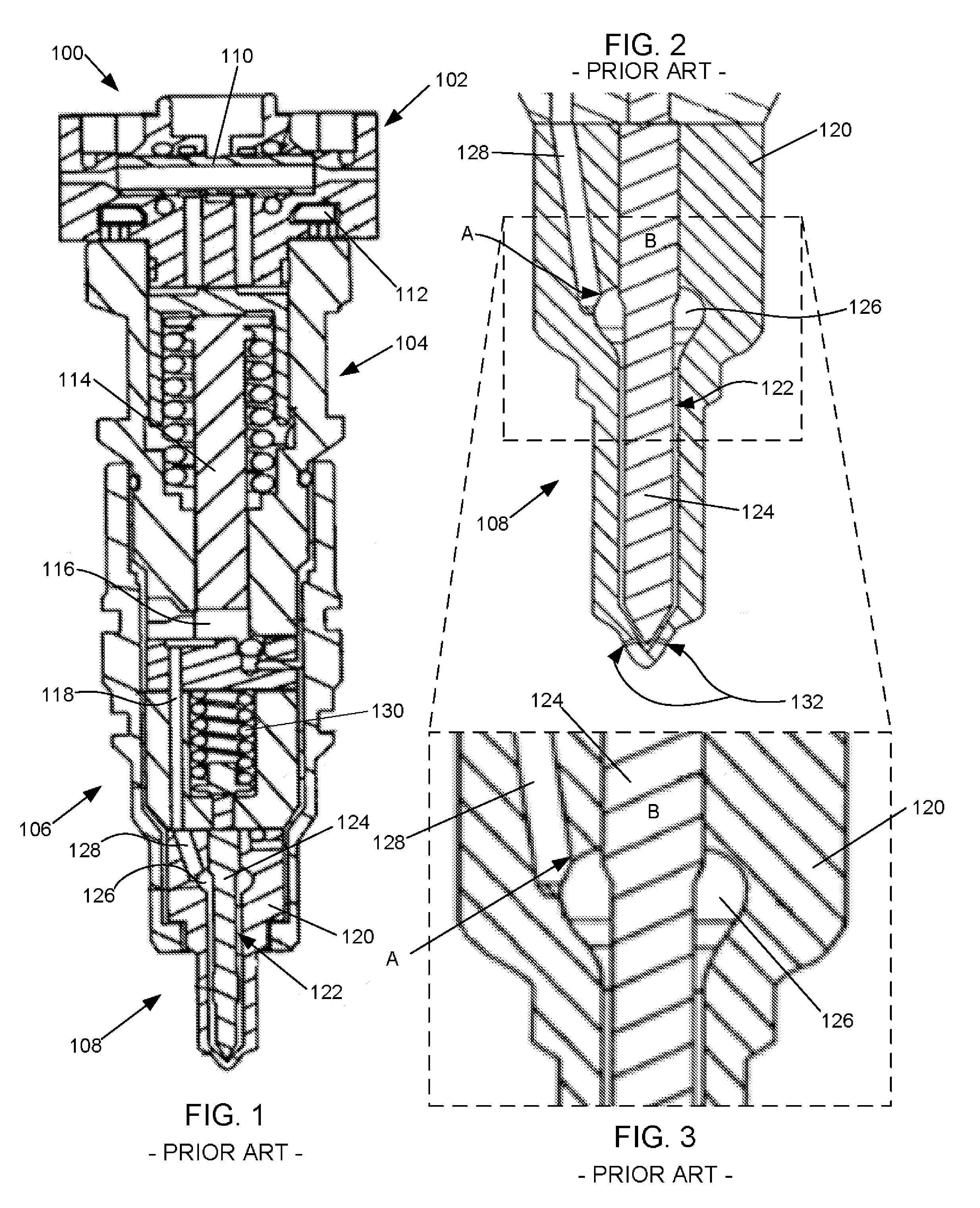
[0012]Various section views of a known fuel injector 100 are shown in FIG. 1, FIG. 2, and FIG. 3 for illustration. The fuel injector 100 is a unit injector capable of injecting fuel at a high pressure. The injector 100 is able to admit fuel at a low pressure and amplify the pressure of the fuel to a high pressure. The fuel injector 100 includes an actuation-fluid valve portion 102, an intensification portion 104, a needle-valve portion 106, and a needle housing portion 108.

[0013]The actuation-valve portion 102 includes a spool valve 110 that is actuated by at least one electronic (e.g. solenoid) actuator 112. During operation of the injector 100, the spo...


PUM


Abstract

A fuel injector for injecting fuel into a cylinder of an internal combustion engine includes an injector body and a needle valve. A feed passage (408) fluidly connects a needle chamber (402) with a source of high pressure fuel. The needle chamber (402) is formed in a needle housing (400) and has a centerline (X) extending along its length. The needle valve is located in the needle chamber (402). A collection cavity (410) is formed in the needle housing (400) and in fluid communication with the needle chamber (402). The collection cavity (410) is positioned between the needle chamber (402) and the feed passage (408). The collection cavity (410) is advantageously substantially symmetrical about a plane that is perpendicular to the centerline (X) of the needle chamber (402).

Description

FIELD OF THE INVENTION[0001]This invention relates to internal combustion engines, including but not limited to needle housings for fuel injectors for use with internal combustion engines.BACKGROUND OF THE INVENTION[0002]Internal combustion engines include crankcases having a plurality of cylinders. The cylinders contain pistons whose reciprocating motion due to combustion events may be transferred through a crankshaft to yield a torque output of the engine. Often, engine crankcases are made of cast metal, and include passages integrally formed therein for the transfer of various fluids from one location of the engine to another. Fluids typically transferred through passages in an engine include coolant, air, fuel, oil, and so forth.[0003]The combustion events within engine cylinders are the result of combustion of a combustible mixture of oxygen and fuel. In modern engines, fuel is injected directly into the cylinder by a fuel injector that is operably associated with each cylinder...

Claims


Application Information

Patent Timeline
Patent Type & Authority Applications(United States)
IPC IPC(8): F02M47/02
CPCF02M55/00F02M57/025F02M61/10F02M2200/40
Inventor ZUKOUSKI, RUSSELL P.OPPERMANN, DEAN A.
Owner INT ENGINE INTPROP CO LLC
Why Eureka
Try Eureka