Spacecraft low tumble linear release system

a technology of linear release and spacecraft, which is applied in the field of spacecraft mechanisms, can solve the problems of substantial and achieve the effect of constant velocity and constant damped motion of the piston

Active Publication Date: 2008-11-27
THE BOEING CO
View PDF5 Cites 10 Cited by
  • Summary
  • Abstract
  • Description
  • Claims
  • Application Information

AI Technical Summary

Benefits of technology

[0009]Systems and methods for releasing a spacecraft payload at a substantially constant velocity are disclosed. A linear actuator is used that includes a spring loaded and fluid filled chamber. The spring drives against a piston within the chamber that includes a control orifice that restricts the fluid flowing from one side of the piston to the other and results in a substantially constant damped motion of the piston. The piston drives a rod from the chamber that is attached to a capture device that holds a flange of the spacecraft payload. The capture device moves along a linear guide toward an open end. Spring loaded latches are held in a closed position by the side walls of the guide as the capture device moves. The latches release the flange as exit the open end of the guide.

Problems solved by technology

The spring drives against a piston within the chamber that includes a control orifice that restricts the fluid flowing from one side of the piston to the other and results in a substantially constant damped motion of the piston.

Method used


Image

  • Spacecraft low tumble linear release system
  • Spacecraft low tumble linear release system
  • Spacecraft low tumble linear release system

Examples


Embodiment Construction

[0024]1. Overview

[0025]As previously mentioned, embodiments of the present invention are directed to devices and methods that can release a payload from a spacecraft with a substantially constant velocity to minimize imparting any unwanted rotation to the released payload. Embodiments of the invention can be defined by the cooperative operation of a combination of mechanical elements.

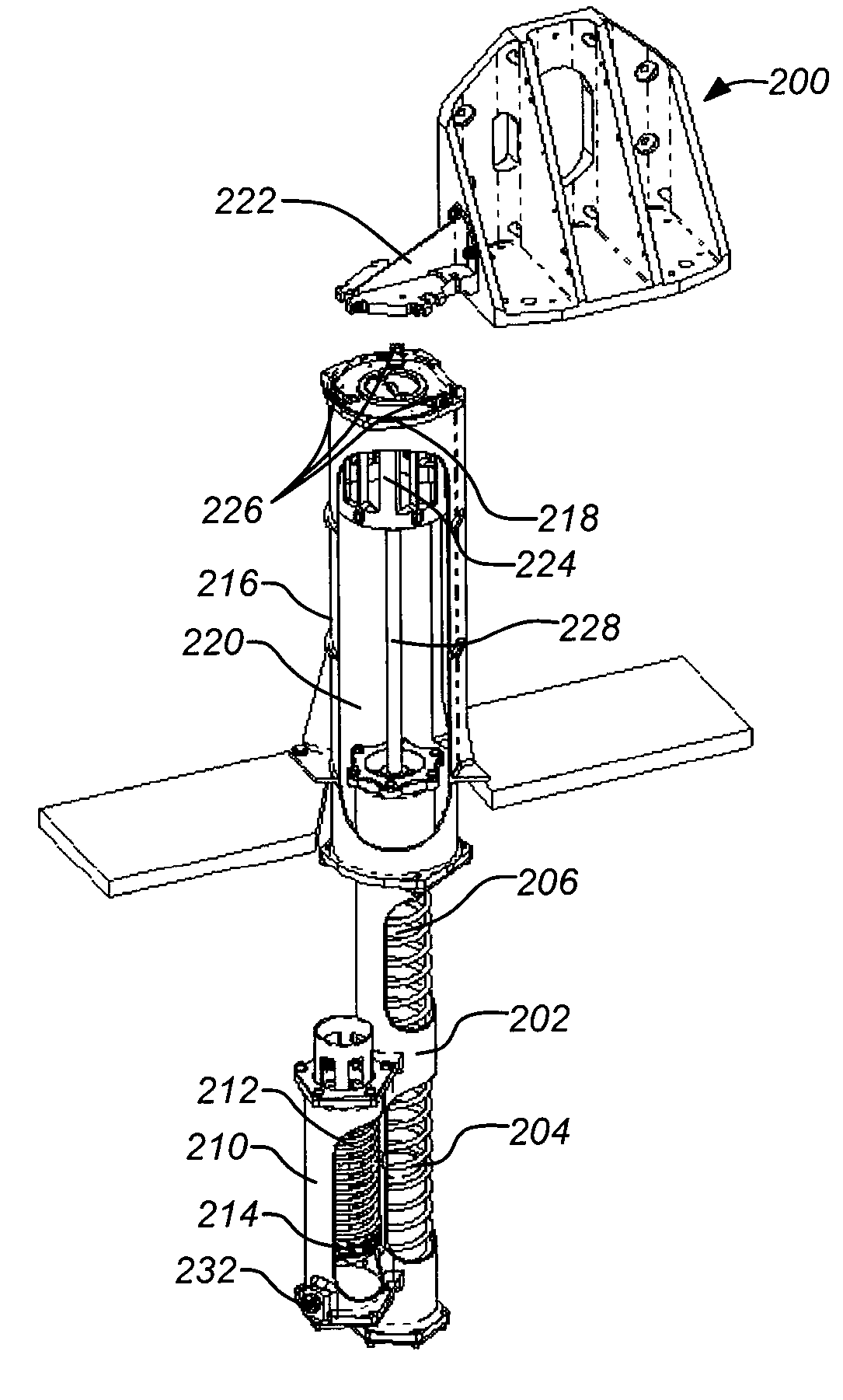
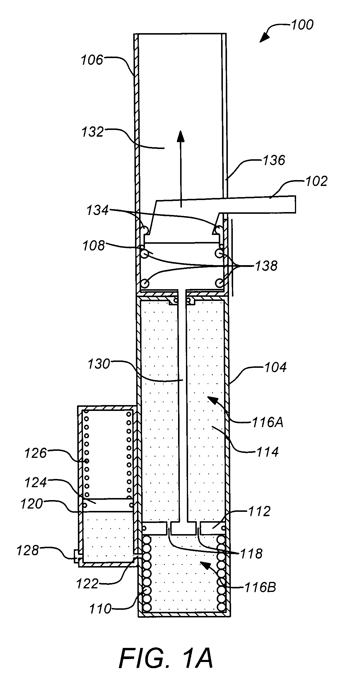
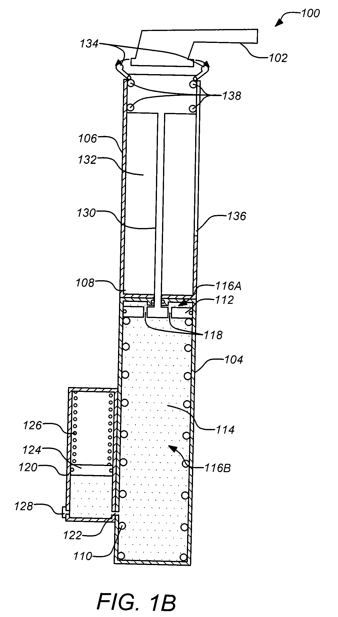
[0026]FIGS. 1A and 1B are functional schematic drawings of an exemplary embodiment of the invention. FIG. 1A illustrates a cut away side view of the release system 100 in the start position. The release system 100 operates on a payload that is coupled to a flange 102. After the payload is released, e.g. at preloaded release bolts located elsewhere, the release system 100 begins to operate automatically as a passive system. The two primary components of the system 100 include a damped actuator 104 and a linear guide 106 (that also operates with a capture device 108). The capture device 108 holds the flan...


PUM


Abstract

Systems and methods for releasing a spacecraft payload at a substantially constant velocity are disclosed. A linear actuator is used that includes a spring loaded and fluid filled chamber. The spring drives against a piston within the chamber that includes a control orifice that restricts the fluid flowing from one side of the piston to the other and results in a substantially constant damped motion of the piston. The piston drives a rod from the chamber that is attached to a capture device that holds a flange of the spacecraft payload. The capture device moves along a linear guide toward an open end. Spring loaded latches are held in a closed position by the side walls of the guide as the capture device moves. The latches release the flange as exit the open end of the guide.

Description

GOVERNMENTS RIGHTS STATEMENT[0001]This invention was made with Government support. The government has certain rights in the invention.BACKGROUND OF THE INVENTION[0002]1. Field of the Invention[0003]This invention relates to mechanisms for spacecraft. Particularly, this invention relates to systems and methods for releasing payloads in space.[0004]2. Description of the Related Art[0005]Separating a major mass item payload from a spacecraft presents a unique problem, particularly if the center of gravity of the payload is not aligned to the separating force vector. Eccentricity of the applied force will impart a rotational motion (or tumble) in addition to the desired linear separating motion which could lead to detrimental recontact of the payload and spacecraft. Other factors can also contribute to undesirable payload tumble.[0006]Spacecraft payloads are often released suddenly by multiple devices that suddenly disengage the payload from the spacecraft at many different points. The ...

Claims


Application Information

Patent Timeline
Patent Type & Authority Applications(United States)
IPC IPC(8): B64G1/64
CPCB64G1/641
Inventor ASTON, RICHARD W.LANGMACK, MICHAELTOTUSEK, TORGER J.
Owner THE BOEING CO
Why Eureka
Try Eureka