Chemical and biological clean air connector

a technology of clean air connectors and connectors, applied in the direction of hose connections, discharge methods of containers, drawing-off water installations, etc., can solve the problems of contamination on the surface of connectors, debilitating or lethal amounts of contaminant into a person's air supply, and the coupling between air supply hoses often needs to be replaced,

Inactive Publication Date: 2008-11-27
AIR LOCK
View PDF19 Cites 41 Cited by
  • Summary
  • Abstract
  • Description
  • Claims
  • Application Information

AI Technical Summary

Problems solved by technology

Some contaminants are so toxic that even introduction of minute amounts of the contaminant into a person's air supply can be debilitating or lethal.
Couplings between air supply hoses often need to be made within a contaminated environment.
Under these conditions, contaminants on the surfaces of the connector can be introduced into the air stream as the coupling is formed.
Preventing such introduction is a difficult problem.

Method used


Image

  • Chemical and biological clean air connector
  • Chemical and biological clean air connector
  • Chemical and biological clean air connector

Examples


Embodiment Construction

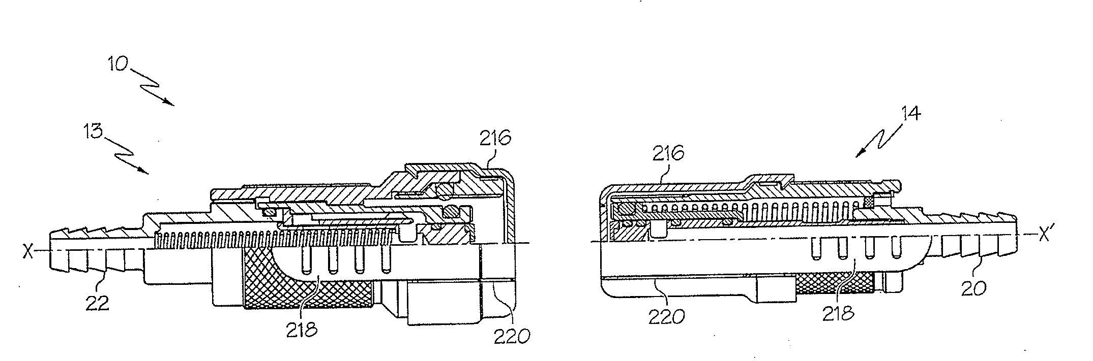
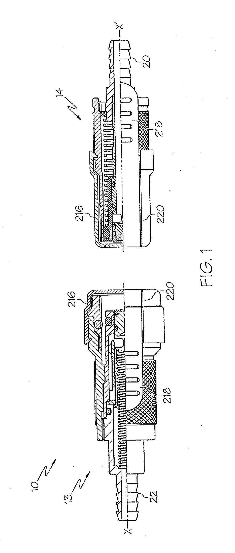
[0059]The present invention as described below is applicable to the clean air connector of U.S. Pat. No. 4,949,745 (the '745 patent), incorporated herein by reference. The details of the connection of the clean air connector of the '745 patent are therefore not repeated below. The clean air connector of the present invention provides certain improvements over the clean air connector of the '745 patent.

[0060]FIG. 1 is a schematic partially cut-away cross-sectional and perspective view of a connector 10 in accordance with an embodiment of the invention. The cut-away cross-sectional view is shown above line X-X′, and the perspective view is shown below line X-X′. The connector includes two subassemblies 13 and 14, with the direction of fluid flow in the assembled connector being from subassembly 13 to subassembly 14. Subassembly 13 is the supply end of the connector 10 and subassembly 14 is the receiver end of the connector 10. Subassembly 13 includes a barbed hose end 22 which is desi...


PUM


Abstract

A connector for use in a contaminated environment is provided. The connector includes first and second couplers which are coupled together to produce a fluid path through the connector. Prior to coupling of the first and second couplers, the first and second couplers include plastic caps for minimizing the contaminants on the couplers. Elastomer face seals which can be contaminated are mated against one another compressing to expel contaminants and trapping contaminants between the elastomer face seals. The elastomer face seals are captured between a pair of O-rings. Parts of the elastomer face seals are flushed with fluid as the connector is coupled to further reduce contamination. All internal passages and the elastomer face seals are treated with an antimicrobial compound. The connector vents to the atmosphere during engagement of the first and second couplers such that the connector can operate at a higher pressure with reduced engagement force.

Description

BACKGROUND OF THE INVENTION[0001]1. Field of the Invention[0002]This invention relates generally to connectors or couplings for joining together the ends of two hoses, tubes or the like. This invention relates in particular to a connector which is of the quick connect / disconnect type, is used as part of a system for supplying air to a person in a contaminated environment, and prevents chemical and biological contaminants in the environment from entering into the air supply as the coupling between hoses is formed.[0003]2. Description of the Related Art[0004]Clean air supplies are needed by persons working in contaminated environments as well as by military personnel in situations where biological or chemical weapons are employed. Some contaminants are so toxic that even introduction of minute amounts of the contaminant into a person's air supply can be debilitating or lethal.[0005]Couplings between air supply hoses often need to be made within a contaminated environment. Under these ...

Claims


Application Information

Patent Timeline
Patent Type & Authority Applications(United States)
IPC IPC(8): F16L35/00
CPCA61M39/18A61M2039/1027F16L37/34F16L2201/44Y10T137/0447
Inventor MCKEON, III, JOHN J.
Owner AIR LOCK
Why Eureka
Try Eureka