Electric current sensor

a technology of current sensor and open-loop sensor, which is applied in the direction of measurement devices, instruments, and measurement using dc-ac conversion, can solve the problems of insufficient robustness for certain uses, affecting measurement accuracy, and relatively expensive manufacturing of conventional open-loop sensors of the above-mentioned type, so as to avoid material waste, easy to automate, and simple operation

Active Publication Date: 2008-11-27
LEM INT SA
View PDF6 Cites 13 Cited by
  • Summary
  • Abstract
  • Description
  • Claims
  • Application Information

AI Technical Summary

Benefits of technology

[0015]The magnetic core may advantageously be formed of a solid filament of magnetic material that undergoes cutting and folding operations which are relatively simple operations that are easy to automate and that do not give rise to wastage of material.
[0016]In another aspect of the invention, the magnetic field detector comprises a detector cell that is surface mounted on a support board, e.g. a printed circuit board, the board being provided with a notch serving to receive one end of the core of the magnetic circuit, so that only the detector cell is inserted into the air-gap. Surface mounting, by using surface mount device (SMD) technology, makes it possible for the detector cell and the support board to be assembled automatically and for the detector cell to be positioned accurately on the support board, and also for the cell to be positioned accurately in the air-gap. The notch may also serve as a reference surface for positioning the magnetic circuit relative to the detector cell. This configuration also makes axial mounting, i.e. mounting that is essentially orthogonal to the midplane of the magnetic circuit, possible for the various components, in particular the magnetic field detector, the magnetic circuit, the lid, and the housing.
[0017]Sealing or welding the lid to the housing by ultrasound makes it possible to achieve good airtightness for the sensor while avoiding the need to fill a housing with resin, which suffers from the disadvantage of exerting mechanical stresses, in particular thermal stresses and / or stresses due to humidity, to the components inside the housing. Furthermore, the method of assembly is simplified and more conducive to mass production.

Problems solved by technology

Conventional open-loop sensors of the above-mentioned type are relatively costly to manufacture due to the cost of manufacturing laminate magnetic circuits and due to cost of assembling the various components, in particular the Hall cell and the magnetic circuit in a housing, while complying with the dimensions and the tolerances of the air-gap and with the position of the Hall cell for guaranteeing good measurement accuracy.
Another problem with conventional open-loop current sensors is that they are not robust enough for certain uses, e.g. for use in the automobile field in which components must be capable of withstanding impacts and vibration without losing measurement accuracy.
However, that can have detrimental consequences on measurement accuracy because of the different coefficients of expansion, in particular the different thermal and / or humidity coefficients of expansion, of the magnetic circuit, of the resin, and / or of the housing, giving rise to mechanical stresses being exerted on the magnetic circuit.
Variation in the air-gap due to such stresses gives rise to errors in measuring the magnetic induction and thus in measuring the electric current.

Method used


Image

  • Electric current sensor
  • Electric current sensor
  • Electric current sensor

Examples


Embodiment Construction

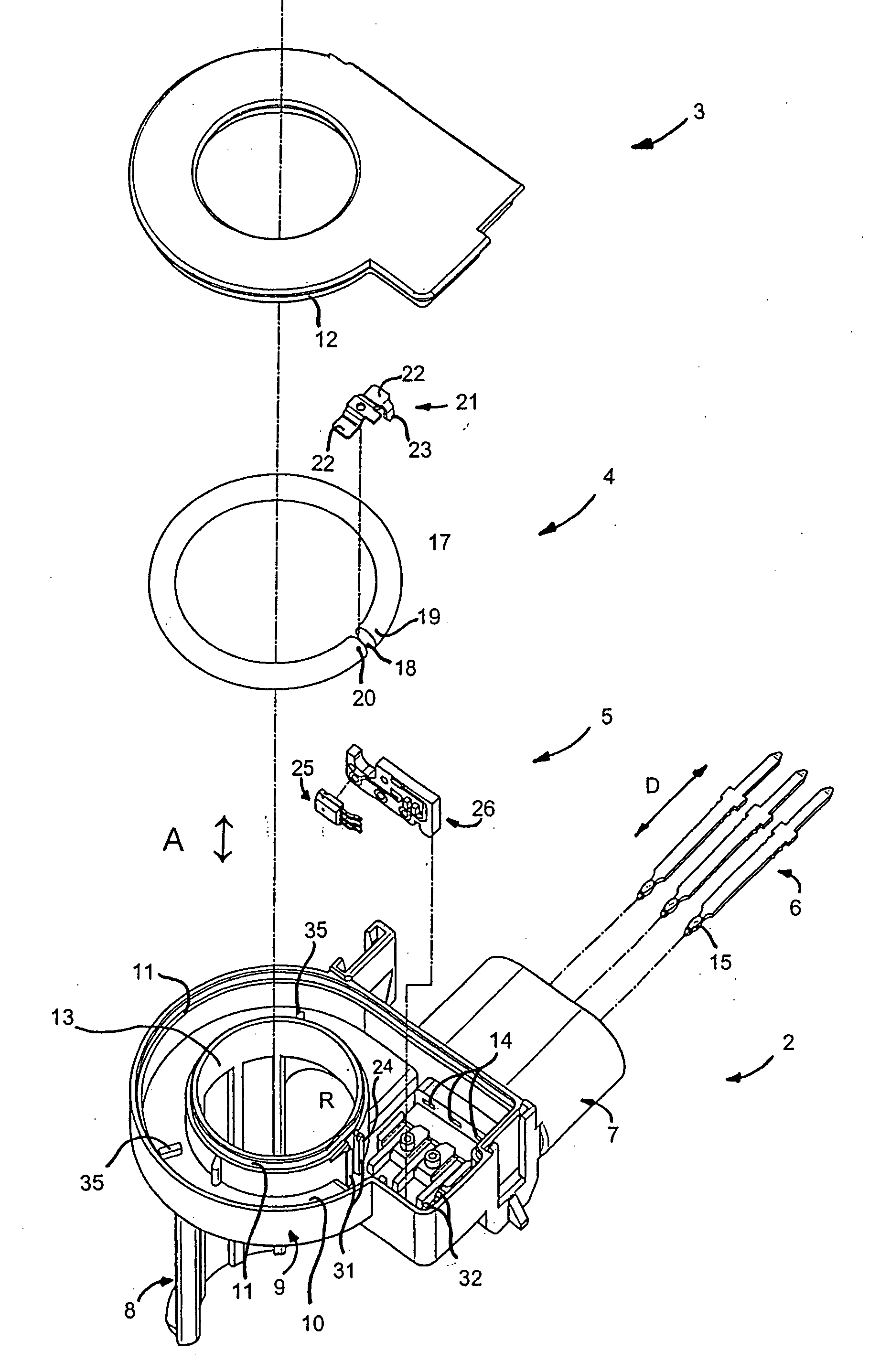
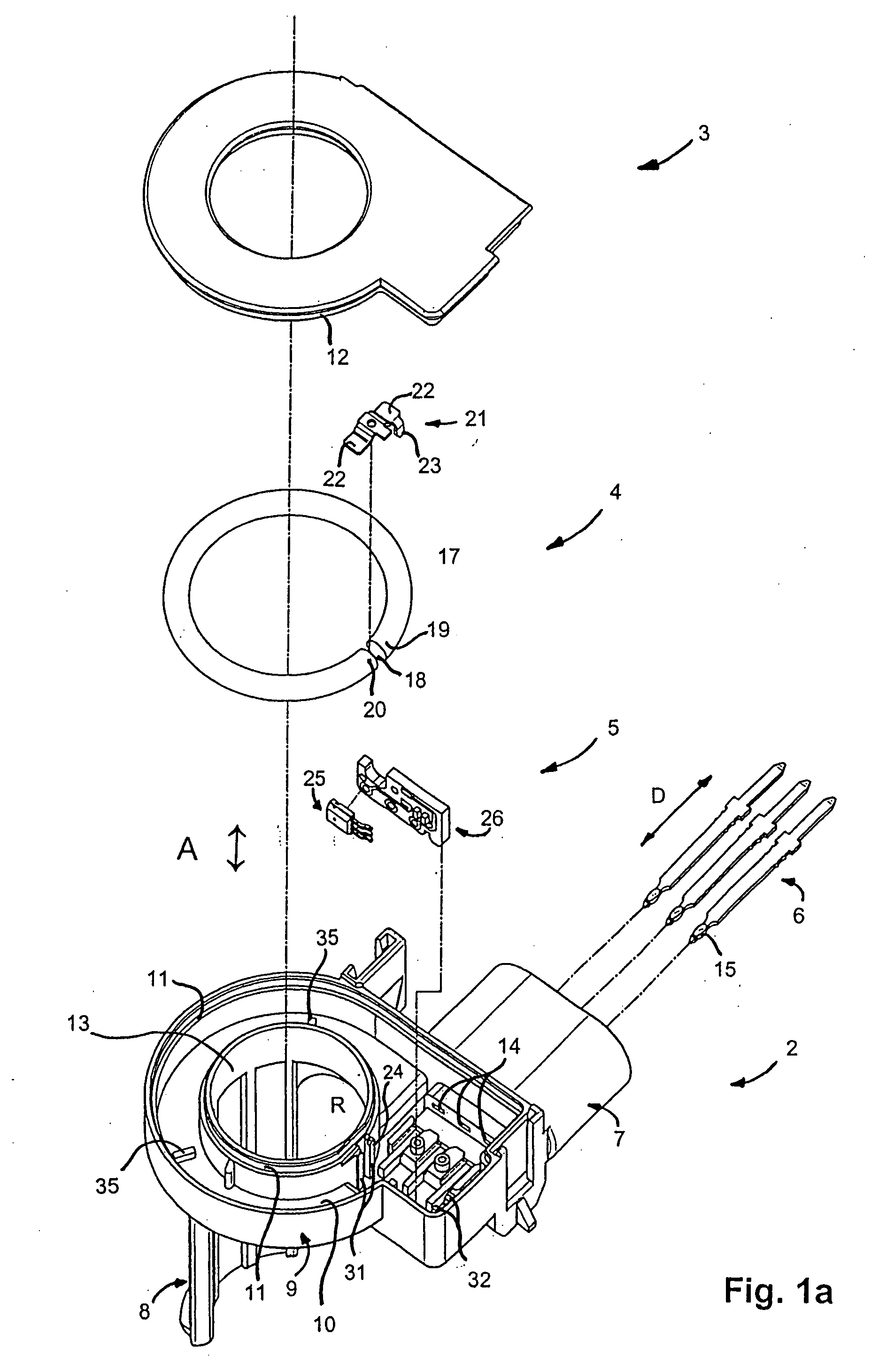
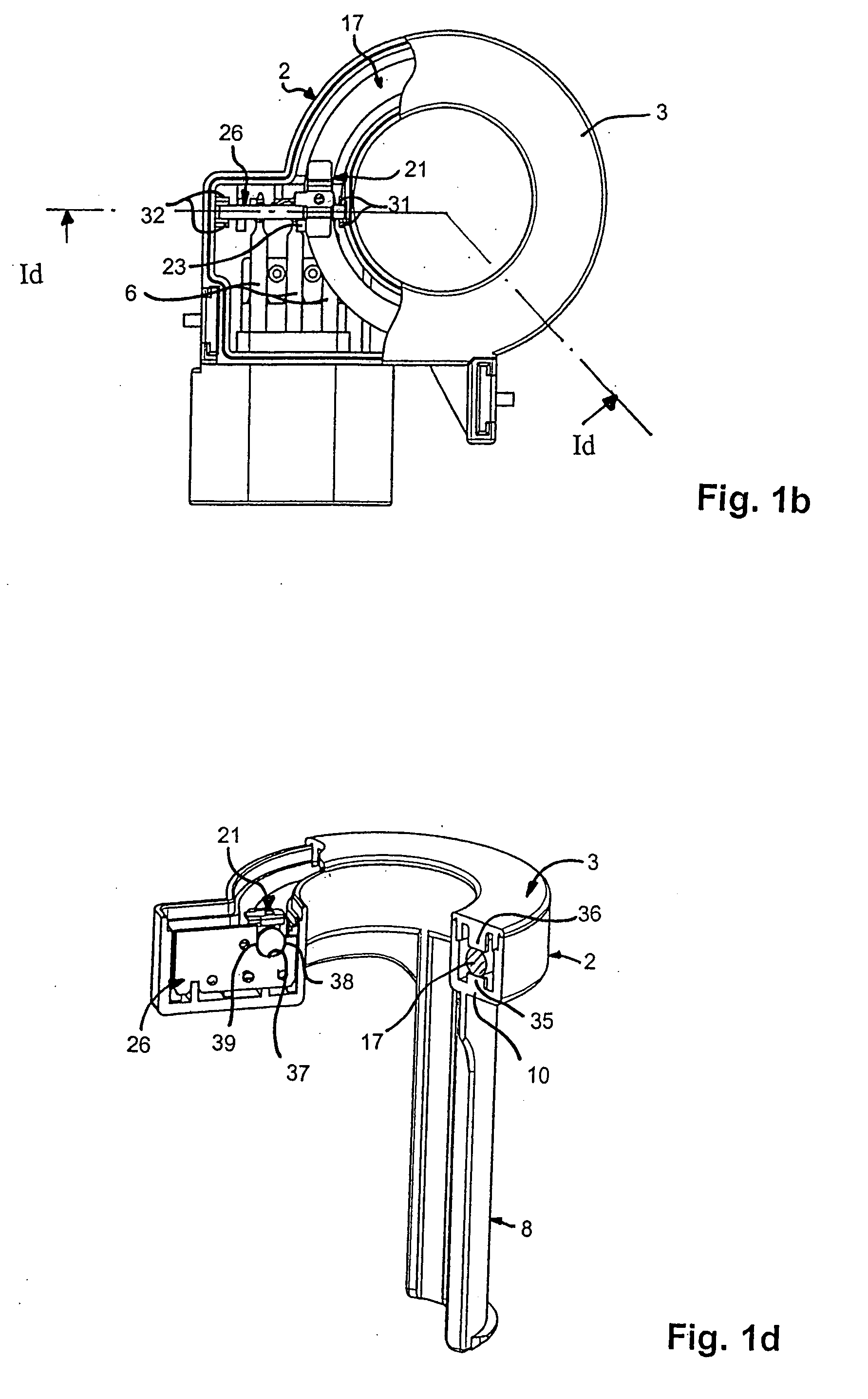
[0026]With reference to the figures, and in particular FIGS. 1a-1d, a current sensor 1 comprises a housing 2, a lid 3, a magnetic circuit 4, a magnetic field detector 5, and connection terminals 6.

[0027]The housing 2 has a connector portion 7, a fastening or support portion 8, and a body portion 9 defining a recess 10 in which the magnetic circuit 4 and the magnetic field detector 5 are mounted. The lid 3 is designed to close the open side 11 of the body portion 9, the body portion being provided with a rim 11 in which a complementary rim 12 on the lid 3 is received.

[0028]The body portion 9 is provided with a central opening 13 serving to pass a conductor along which the current to be measured flows. In the example shown, the conductor can, in particular, be a cable, e.g. the power supply cable of an automobile battery, the sensor delivering information to a system for managing and monitoring the battery. The support or fastening portion 8, which is in the form of a curved wall exte...


PUM


Abstract

An electric current sensor having a housing, magnetic circuit with a magnetic core, and a magnetic field detector with a detection cell, positioned in an air gap between ends of the core. The core is made of a non-laminated magnetic material, and the magnetic circuit has a strap made of non-magnetic material welded to the core at each side of the air gap. The magnetic field detector has a support plate on which the detection cell is mounted. The plate has a recess, opposition the detection cell, which houses one end of the magnetic circuit.

Description

[0001]This application is a divisional application from co-pending U.S. patent application Ser. No. 10 / 546,907, and Applicants claim foreign priority benefits under 35 U.S.C. §§119(a)-(d) or (f), or §365(b) of European Patent Application No. 03004186.7, filed Feb. 27, 2003.[0002]The present invention relates to an electric current sensor, in particular an open-loop electric current sensor.BACKGROUND OF THE INVENTION[0003]Numerous open-loop current sensors exist comprising a magnetic circuit having an air-gap and a Hall cell disposed in the air-gap for measuring the magnetic field induced by an electric current flowing along a conductor passing through the magnetic circuit. The magnetic circuit is typically made of a material that conducts magnetic flux, i.e. a “magnetic material”, and that is laminate. The Hall cell can have electrical terminals in the form of pins mounted orthogonally on a printed circuit.[0004]Conventional open-loop sensors of the above-mentioned type are relative...

Claims


Application Information

Patent Timeline
Patent Type & Authority Applications(United States)
IPC IPC(8): G01R19/00G01R15/20
CPCG01R15/205G01R15/207
Inventor LEPINE, GERARDDE LORIOL, OLIVIERMORET, GILLESCHENAVARD, THIERRY
Owner LEM INT SA
Why Eureka
Try Eureka