This helps you quickly interpret patents by identifying the three key elements:
Problems solved by technology
Method used
Benefits of technology
Benefits of technology
[0070]The video electro-optic displays of the present invention share most of the advantages of prior art electro-optic displays intended for displaying static images. For example, the video displays of the present invention typically have lower power consumption than prior art video displays, since it is only necessary to rewrite the pixels which change between successive images. (Rewriting of unchanging pixels at long intervals of at least seconds may be needed to cope with slow fading of the displays, but the energy used in rewriting at such long intervals is much less than that required in displays, such as those based on non-bistable liquid crystals, which must be rewritten continuously.) Furthermore, freezing individual frames on a bistable display of the present invention is much simpler than on a prior art display, since on the bistable display one can simply stop rewriting the display leaving the desired frozen image in place.
Problems solved by technology
Nevertheless, problems with the long-term image quality of these displays have prevented their widespread usage.
For example, particles that make up electrophoretic displays tend to settle, resulting in inadequate service-life for these displays.
Such gas-based electrophoretic media appear to be susceptible to the same types of problems due to particle settling as liquid-based electrophoretic media, when the media are used in an orientation which permits such settling, for example in a sign where the medium is disposed in a vertical plane.
Indeed, particle settling appears to be a more serious problem in gas-based electrophoretic media than in liquid-based ones, since the lower viscosity of gaseous suspending fluids as compared with liquid ones allows more rapid settling of the electrophoretic particles.
Typically, until now, electrophoretic and other bistable displays have an update time of the order of hundreds of milliseconds so that it has been assumed that such displays are confined to essentially static images and are not capable of displaying video.
However, even the aforementioned paper only claims that near video-rates can be achieved, and the paper is only discussing gray scale displays.
Achieving acceptable video on a color display is considerably more difficult.
However, in the case of a reflective color display, in which only part of the area of the display can display each of the primary colors, it is much less easy to tolerate incomplete driving of the electro-optic medium to its extreme optical states, since such incomplete driving affects not only the contrast ratio of the display but also its color saturation.
Accordingly, it has hitherto appeared that high quality video, and especially high quality color video, is not presently possible on bistable electro-optic displays.
Method used
Image
Click on the blue label to locate the original text in one second.
Reading with bidirectional positioning of images and text.
Examples
Embodiment Construction
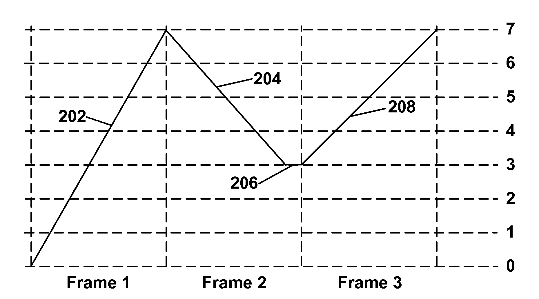
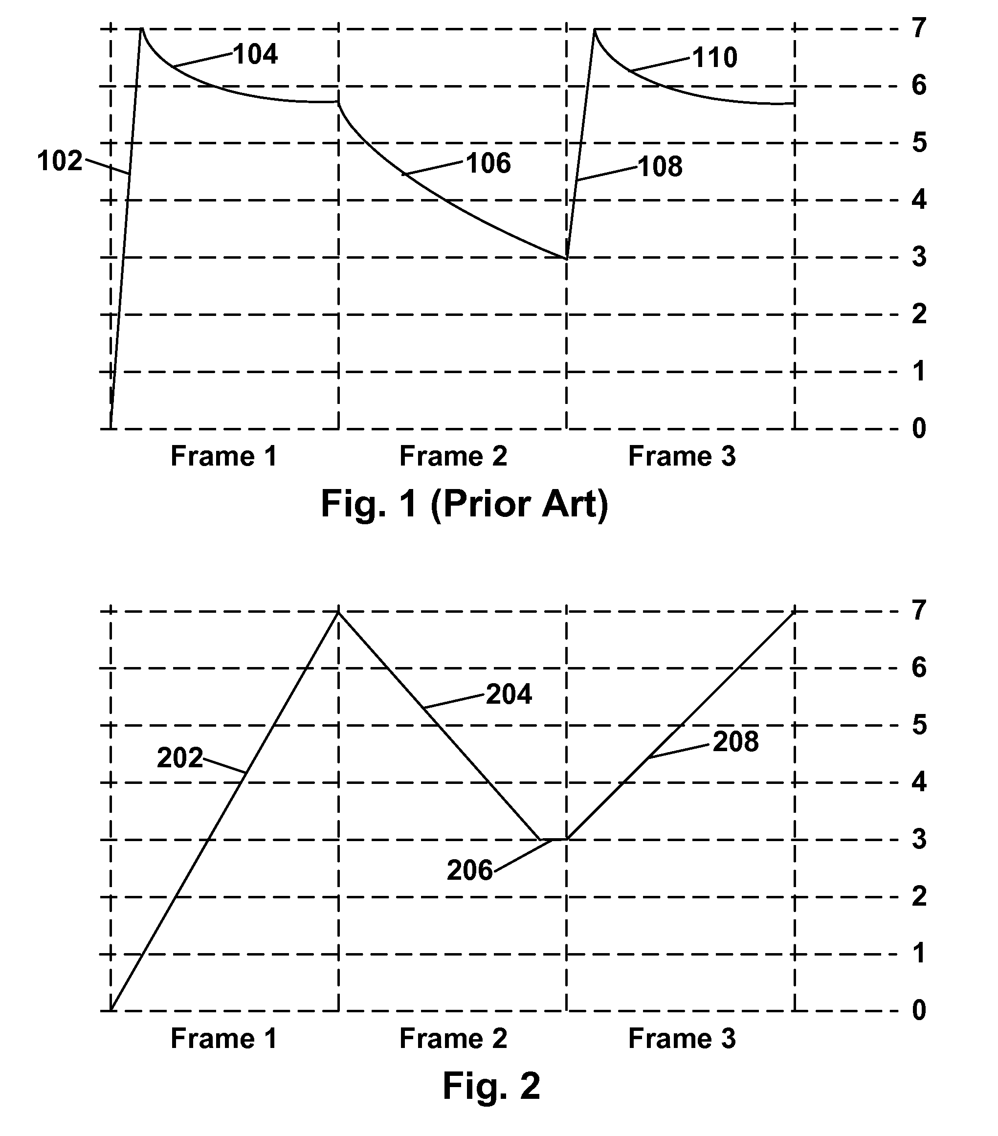
[0054]Conventional video rate displays using non-bistable media, such as the phosphors on cathoderay tubes and conventional liquid crystal displays, require frame rates in excess of about 25 frames per second (fps) to provide acceptable video quality. (Video display at 15 fps is common on internet videos but results in a noticeable lack of video quality.) It has now very surprisingly been found that bistable, and certain other, electro-optic displays can produce good quality images at frame rates substantially below 25 fps, and in the range of about 10 to about 20 fps, preferably about 13 to about 20 fps. Experienced observers have determined that encapsulated electrophoretic displays running at 15 fps can produce video quality which appears substantially equal to that produced by non-bistable displays running at about 30 fps.
[0055]Although the reasons for this unexpectedly high video quality at low frame rates are not at present entirely understood (and the invention is not limite...
PUM
Abstract
Video displays using relatively low frame rates of about 10 to about 20 frames per second, but having acceptable video quality are described. The displays may use bistable media, and may be driven such that the medium, when driven, changes its optical properties continuously during the driving of each frame. The displays may use an electro-optic medium such that the frame period is from about 50 to about 200 percent of the switching time of the electro-optic medium at the driving voltage used.
Description
REFERENCE TO RELATED APPLICATIONS[0001]This application claims benefit of copending Application Ser. No. 60 / 939,187, filed May 21, 2007.[0002]This application is also related to:[0003](a) U.S. Pat. No. 6,504,524;[0004](b) U.S. Pat. No. 6,512,354;[0005](c) U.S. Pat. No. 6,531,997;[0006](d) U.S. Pat. No. 6,995,550;[0007](e) U.S. Pat. Nos. 7,012,600 and 7,312,794, and the related copending applications Ser. Nos. 11 / 307,886 and 11 / 307,887 (Publication Nos. 2006 / 0139310 and 2006 / 0139311 respectively;[0008](f) U.S. Pat. No. 7,034,783;[0009](g) U.S. Pat. No. 7,119,772;[0010](h) U.S. Pat. No. 7,193,625;[0011](i) U.S. Pat. No. 7,259,744;[0012](j) copending application Ser. No. 10 / 879,335 (Publication No. 2005 / 0024353);[0013](k) copending application Ser. No. 10 / 904,707 (Publication No. 2005 / 0179642);[0014](l) copending application Ser. No. 10 / 906,985 (Publication No. 2005 / 0212747);[0015](m) U.S. Pat. No. 7,327,511;[0016](n) copending application Ser. No. 10 / 907,171 (Publication No. 2005 / 0152...
Claims
Application Information
Patent Timeline
Application Date:The date an application was filed.
Publication Date:The date a patent or application was officially published.
First Publication Date:The earliest publication date of a patent with the same application number.
Issue Date:Publication date of the patent grant document.
PCT Entry Date:The Entry date of PCT National Phase.
Estimated Expiry Date:The statutory expiry date of a patent right according to the Patent Law, and it is the longest term of protection that the patent right can achieve without the termination of the patent right due to other reasons(Term extension factor has been taken into account ).
Invalid Date:Actual expiry date is based on effective date or publication date of legal transaction data of invalid patent.

