Support device for supporting propeller shaft and propeller shaft itself
- Summary
- Abstract
- Description
- Claims
- Application Information
AI Technical Summary
Benefits of technology
Problems solved by technology
Method used
Image

Examples
first embodiment
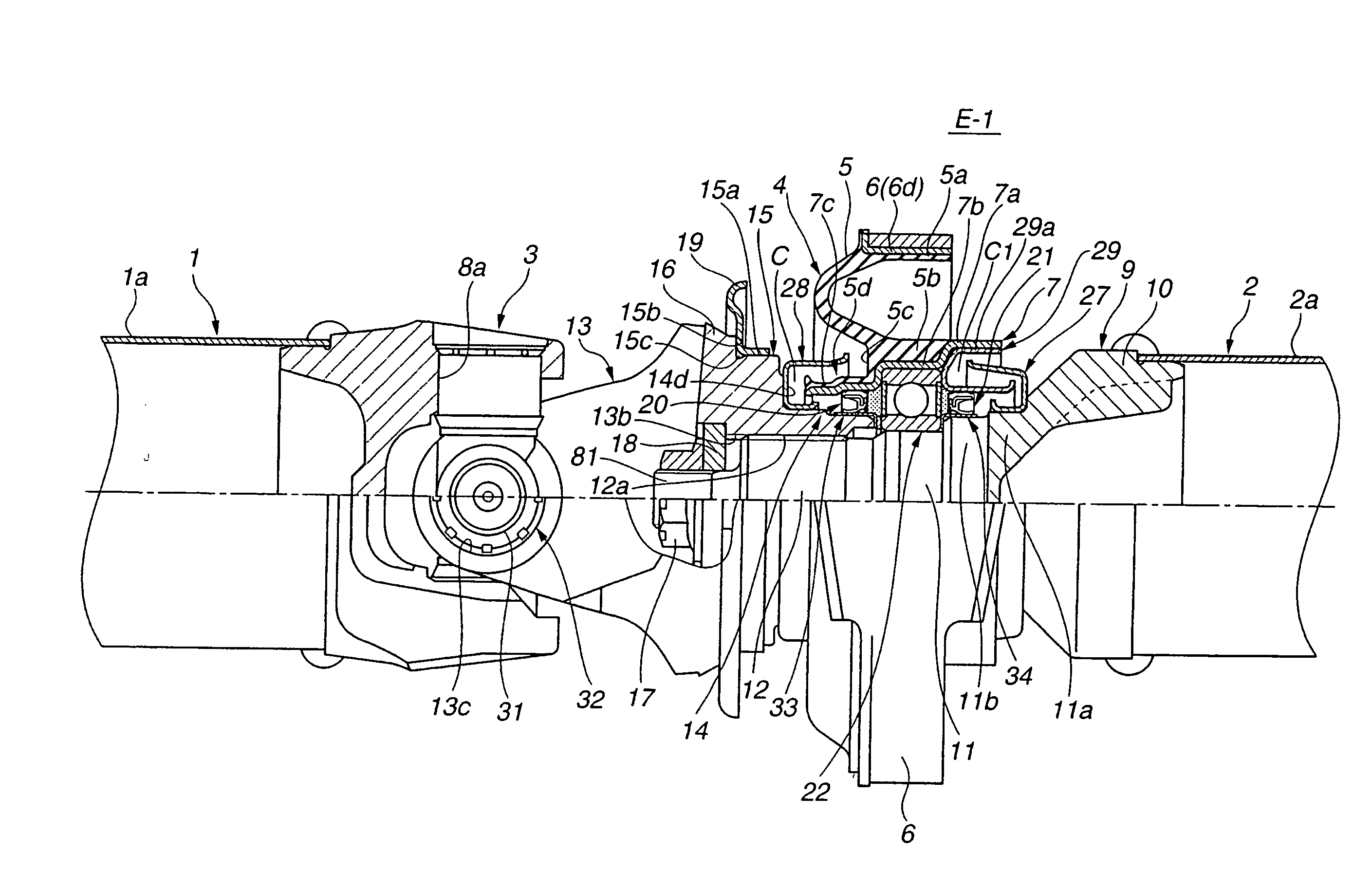
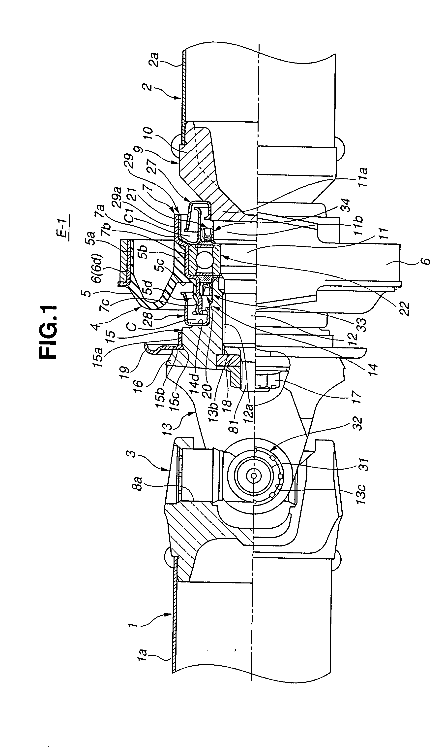
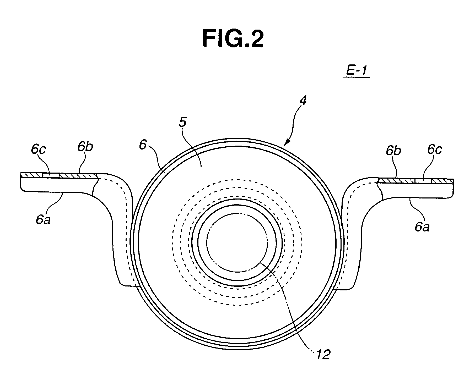
[0070]In the following, the detailed construction of support device 4 of the first embodiment will be described with reference to FIGS. 1 and 3, particularly FIG. 3.
[0071]As is seen from FIGS. 1 and 3, between larger diameter right portion 10 and medium diameter middle portion 11 of stub shaft 9, there is defined a cylindrical portion 11a whose diameter is smaller than that of right portion 10 but larger than that of middle portion 11.
[0072]As is best seen from FIG. 3, between cylindrical portion 11a and middle portion 11 of stub shaft 9, there is defined a cylindrical portion 11b whose diameter is smaller than that of cylindrical portion 11a but larger than that of middle portion 11.
[0073]Around middle portion 11 of stub shaft 9, there is disposed a radial ball bearing unit 22. As will be clarified hereinafter, radial ball bearing unit 22 constitutes part of the support device 4 of the invention.
[0074]Around cylindrical portion 11a of stub shaft 9, there is tightly disposed a first...
second embodiment
[0125]Referring to FIG. 5, there is shown a support device E-2 of the present invention.
[0126]Since this second embodiment E-2 is similar to the above-mentioned first embodiment E-1, only portions or elements that are different from those of the first embodiment E-1 will be described in detail in the following.
[0127]As is seen from FIG. 5, in the second embodiment E-2, two rust-proofing cylindrical members 34 and 33 are made of a low friction material, such as polyacetal resin or the like.
[0128]Furthermore, in this second embodiment E-2, there is no member that corresponds to annular plate 30 used in the first embodiment E-1, and thus, annular flange portion 33b of rust-proofing cylindrical member 33 is in contact with the left end surface of inner race 23 of radial ball bearing unit 22, as shown.
[0129]That is, in the second embodiment E-2, the two rust-proofing cylindrical members 34 and 33 have a surface friction coefficient lower than that of end surfaces 23c and 23d of inner rac...
third embodiment
[0138]Referring to FIG. 6, there is shown a support device E-3 of the present invention.
[0139]Since this third embodiment E-3 is similar to the above-mentioned first embodiment E-1, only portions that are different from those of the first embodiment E-1 will be described in detail in the following.
[0140]As is seen from FIG. 6, in the third embodiment E-3, each of two rust-proofing cylindrical members 34 and 33 has at an axially outer end 34e or 33e an outer annular flange portion 34f or 33f that extends radially outward.
[0141]Furthermore, outer annular flange portion 34f is placed between a right end of annular seal member 21 and a raised left end of inner cylindrical portion 27a of first annular dust cover 27 in such a manner as to almost shut a terminal part of the complicated path “C1” of the labyrinth structure, and similar to this, the other outer annular flange portion 33f is placed between a left end of annular seal member 20 and a raised right end of inner cylindrical portio...
PUM
 Abstract
Description
Claims
Application Information
PatSnap Eureka turns technology decisions into work you can execute. Powered by our Innovation Knowledge Graph, it runs expert workflows across engineering, life sciences, materials and intellectual property. Get your review-ready output in minutes.


