Pedicle screw fixation system

a technology of fixing system and screw, which is applied in the field of spine fixing system, can solve the problems of requiring torque to tighten the locking element, rarely allowing three or more implants to be directly in line, and requiring a significant amount of torque in the final tightening

Active Publication Date: 2008-11-27
AESCULAP IMPLANT SYST
View PDF14 Cites 81 Cited by
  • Summary
  • Abstract
  • Description
  • Claims
  • Application Information

AI Technical Summary

Benefits of technology

[0010]The foregoing drawbacks and the needs to improve on known fixation systems and techniques are resolved to a large degree by a fixation system and locking mechanism in accordance with the present invention.

Problems solved by technology

The spine anatomy, however, rarely allows for three or more implants to be directly in line.
One drawback of this construct, and of all systems that utilize set screws or other rotating locking elements, is the requirement of torque to tighten the locking element.
A significant amount of torque is typically applied in the final tightening.
This introduces a substantial risk of “blowout”, in which torque and / or other components of force tilt the shank out of its set alignment in the screw hole, causing the shank to break through the relatively thin bone wall of the pedicle.
In such a case, removal and resetting of the polyaxial screw can exacerbate the trauma to the bone.
This requires the careful balancing of torque with countertorque, and any imbalance can still cause blowout.
Aside from the obvious disadvantage of adding to instrument costs and instrument preparation, the countertorque instrument can be cumbersome to use while advancing the locking element at the same time.
This may compel the need for additional medical personnel during installation of the fixing assembly.
The countertorque instrument further adds to the visual obstructions over the incision, and may require the size of the incision to be made larger to accommodate the additional instrumentation.
Systems that use threaded locking mechanisms are also difficult to use, requiring precise coordination and mating of components.
In many cases, the assembly is very small, and proper thread starting can be difficult.
If the threading is not started properly, the locking mechanism can bind, damaging the threaded surfaces and rendering the components unusable.

Method used


Image

  • Pedicle screw fixation system
  • Pedicle screw fixation system
  • Pedicle screw fixation system

Examples


Embodiment Construction

[0029]Although the invention is illustrated and described herein with reference to specific embodiments, the invention is not intended to be limited to the details shown. Rather, various modifications may be made in the details within the scope and range of equivalents of the claims and without departing from the invention.

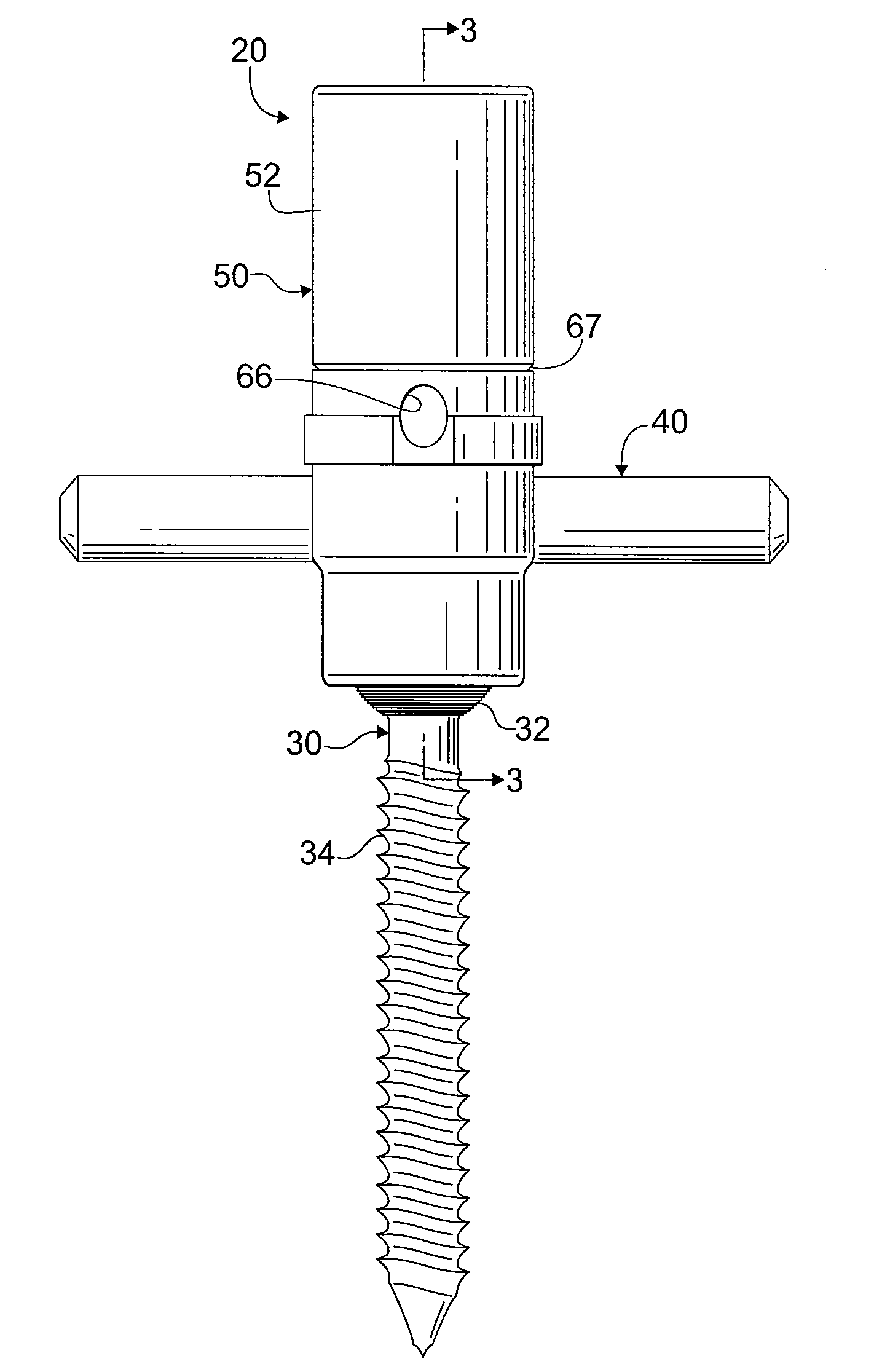
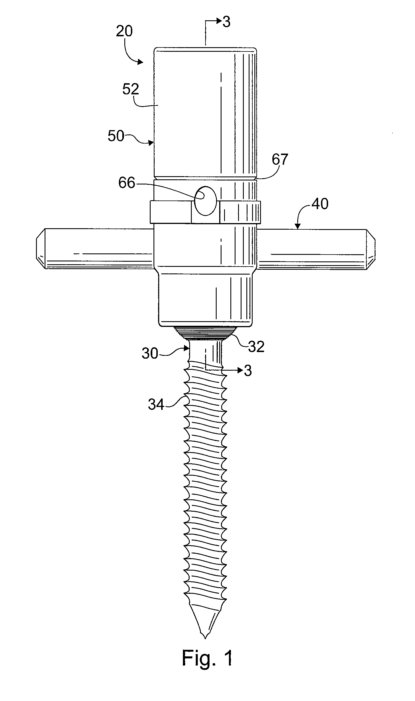
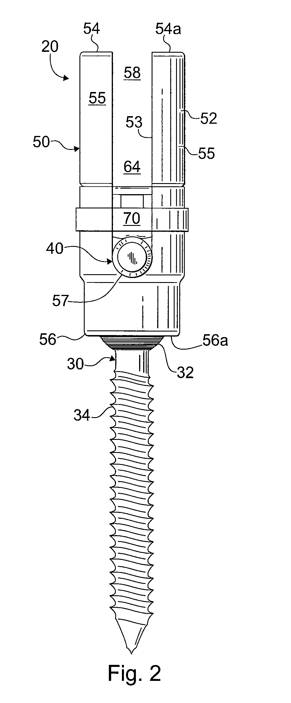
[0030]Referring to the drawing figures generally, and to FIGS. 1 and 2 in particular, a fixation assembly 20 in accordance with an exemplary embodiment of the invention is shown. Fixation assembly 20 includes a polyaxial screw 30 and a hollow receiver component 50. Polyaxial screw 30 has a screw head 32 that is seated inside the receiver component 50, and a threaded shank 34 that projects outside the receiver component. Receiver component 50 supports a rod 40 that may be coupled to two or more polyaxial screws for stabilizing and correcting the spine at multiple levels and locations. Rod 40 is secured in receiver component 50 by a locking mechanism 70. As will be ...


PUM


Abstract

A locking mechanism for locking a rod in a screw and rod fixation assembly includes a cap having a sidewall and a locking element extending from at least a portion of the sidewall. Locking mechanism cooperates with a receiver component for a spinal fixation rod to lock the rod in the receiver without requiring application of torque. A method of locking a spinal fixation member in a receiver of a screw fixation assembly includes the steps of placing the spinal fixation member into a channel of a receiver, axially advancing a locking cap into the receiver toward the spinal fixation member without application of any torque, and securing the locking cap in a locked position above the spinal fixation member without application of any torque.

Description

FIELD OF THE INVENTION[0001]The invention relates to fixation systems for the spine, and more particularly to a screw fixation system with a locking mechanism that can be tightly secured without applying torque.BACKGROUND OF THE INVENTION[0002]Several techniques and systems have been developed for correcting and stabilizing the spine and for facilitating fusion at various levels of the spine. Stabilization of the spine for various conditions, including degenerative disk disease, scoliosis, spondylolisthesis, and spinal stenosis, often require attaching implants to the spine and then securing the implants to spinal rods. Such spinal fixation devices can immobilize the vertebrae of the spine and can alter the alignment of the spine over a large number of vertebrae by connecting at least one elongate rod to the sequence of selected vertebrae. These rods can span a large number of vertebrae, such as three or four. The spine anatomy, however, rarely allows for three or more implants to b...

Claims


Application Information

Patent Timeline
Patent Type & Authority Applications(United States)
IPC IPC(8): A61B17/04A61B17/58
CPCA61B17/7032A61B17/7037A61B2017/00867A61B2019/307A61B2090/037
Inventor KOVACH, MATTHEWWEAVER, PAUL
Owner AESCULAP IMPLANT SYST
Why Eureka
Try Eureka