Attachment system for a modular flooring assembly

a technology of modular flooring and attachment system, which is applied in the direction of floors, building components, floors, etc., can solve the problems of reducing the enjoyment of the floor, the system employing tongue and groove engagement, and the practicality of modular flooring assembly, so as to achieve convenient disassembly and transportation, enhance portability, and secure and smooth floor surface

Inactive Publication Date: 2008-12-04
DAGGER ROBERT K
View PDF11 Cites 23 Cited by
  • Summary
  • Abstract
  • Description
  • Claims
  • Application Information

AI Technical Summary

Benefits of technology

[0009]The present invention is related to an attachment system, and a modular flooring assembly using the same, to provide a secure and smooth floor surface. The modular flooring assembly of the present invention can be readily disassembled and transported for re-assembly at a different location for enhanced portability. The modular flooring assembly of the present invention includes a plurality of floor members adapted for adjoining edge-to-edge engagement to form a corresponding joint therebetween, a resilient, elastic material supporting the bottom portion of the floor members to impart a spring action to the floor members, and an attachment system comprising a clip configured to operatively engage adjoining floor members to securely retain the engaged floor members in juxtaposition and prevent lateral separation to form a floor surface without any open joints or seams, holes, raised surfaces or objects that may obstruct the user.
[0010]The modular flooring assembly of the present invention is further designed to impart a force absorbing spring to the floor surface to enhance the action, feel and appearance of the floor that is especially desirable for dancing and theatrical performances. The modular flooring assembly of the present invention is adapted to withstand forces of wear and tear associated with user activity thereon. The arrangement of the floor members and the attachment system comprising one or more clips in accordance with the present invention greatly enhances ease of maintenance and care of the floor surface. The modular flooring assembly of the present invention is simple to assemble and disassemble using minimal tools, hardware and labor to implement.
[0016]the pair of legs each further configured for operative engagement with the top portions of corresponding one of adjacently adjoined floor members to securely retain the engaged floor members in juxtaposition, while permitting radial movement of the adjoined floor members about their common joint.
[0024]the pair of legs each further configured for operative engagement with the top portions of corresponding one of adjacently adjoined floor members to securely retain the engaged floor members in juxtaposition, while permitting radial movement of the adjoined floor members about their common joint.

Problems solved by technology

However, despite their convenience, modular flooring assemblies designed especially for dancing, present a unique set of challenges.
There are several disadvantages in attachment systems employing tongue and groove engagement.
First, such systems require the use of tools and hardware (i.e., screw or bolt fasteners) for securing the flooring members together.
The practicality of modular flooring assemblies is frustrated, if the tools and / or hardware are lost or misplaced causing either delays or improper assembly, which may be unsafe and may greatly reduce enjoyment of the floor.
Second, assembly and disassembly is slow and tedious with such systems, since each screw or bolt fastener must be individually introduced and tightened during assembly, or loosened for removal during disassembly.
Third, a screw or bolt head, which is not entirely flush with the surface of the dance floor, creates a potential hazard for the user.
Fourth, when the floor is not in use, the tools and hardware must be stored such that they are readily located for the nest use.

Method used


Image

  • Attachment system for a modular flooring assembly
  • Attachment system for a modular flooring assembly
  • Attachment system for a modular flooring assembly

Examples


Embodiment Construction

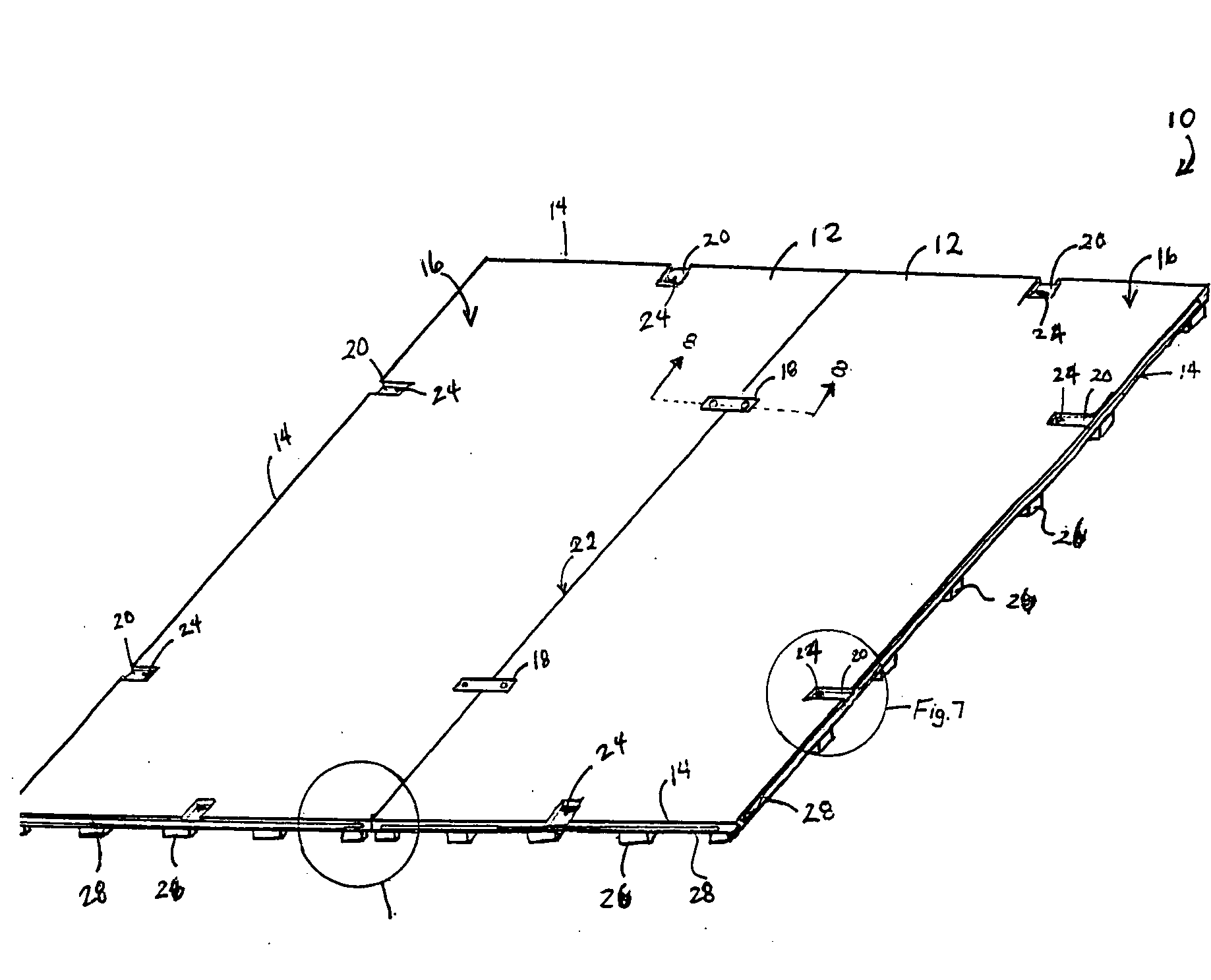
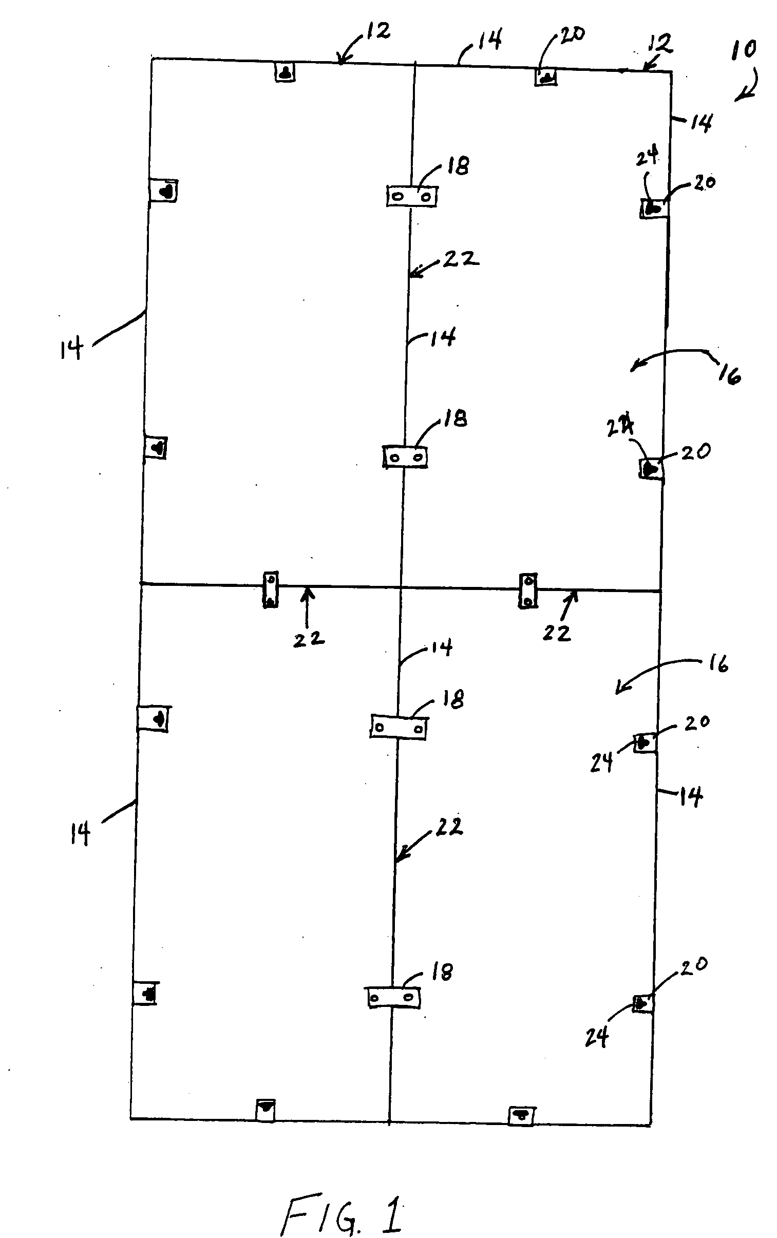
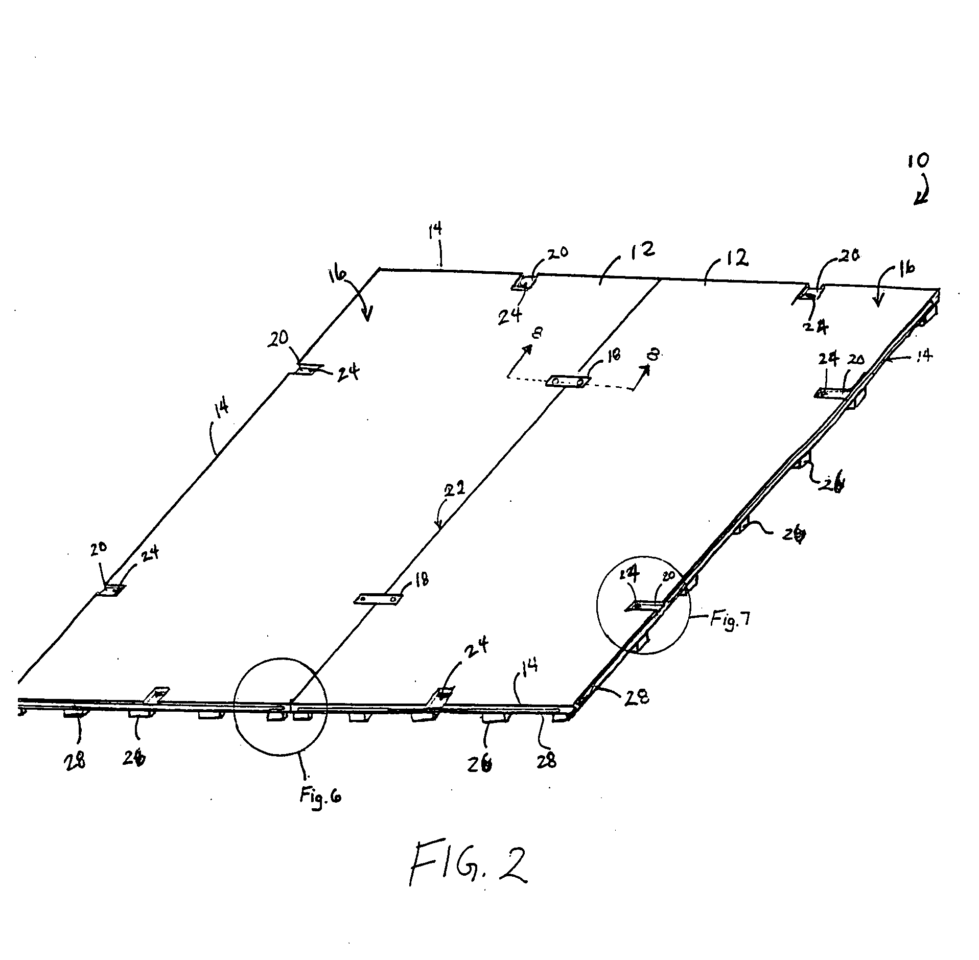
[0034]The present invention is directed to a modular flooring assembly and an attachment system for the modular flooring assembly comprises a clip to provide a secure and smooth floor surface. The modular flooring assembly may be readily disassembled and transported for re-assembly at a different location for enhanced portability. The modular flooring assembly of the present invention includes a plurality of floor members adapted for adjoining edge-to-edge engagement to form a corresponding joint therebetween, a resilient, elastic material supporting the bottom portion of the floor members to impart a spring action to the floor members, and an attachment system comprising a clip configured to operatively engage adjoining floor members to securely retain the engaged floor members in juxtaposition and prevent lateral separation to form a floor surface without any open joints or seams, holes, raised surfaces or objects.

[0035]The attachment system of the present invention comprises a cl...


PUM


Abstract

A modular flooring assembly, includes at least two floor members, each including top and bottom portions, and edge portions configured for operative engagement with the edge portion of an adjacent floor member to form a common joint, wherein the engaged edge portions are further configured for facilitating radial movement of the juxtaposed floor members about the common joint, a resilient, elastic material supporting the bottom portion of the floor members in contact with the ground, and an attachment system including clip with a cross-piece member having first and second ends, a pair of opposed legs, each extending from the corresponding first and second ends inwardly toward one another, and the legs each configured for operatively engaging the top portions of corresponding one of adjacent floor members to securely retain the engaged floor members in juxtaposition and prevent lateral separation, while permitting radial movement of the adjacent floor members about their common joint.

Description

FIELD OF THE INVENTION[0001]The present invention relates to flooring assemblies, and more particularly, an attachment system for a modular flooring assembly.BACKGROUND OF THE INVENTION[0002]Modular flooring assemblies are constructed from substantially flat floor sections or members extending over an area of the subfloor in an interlocking arrangement. Typically, the assembled floor members remain detached from the subfloor to provide a floating floor construction. A base floor material comprising a resilient friction-producing material such as, for example, cardboard, felt, cork or foam plastic is placed between the floor members and the subfloor to match the contour of the subfloor, and smooth out any irregularities in the surface of the subfloor. This keeps the modular flooring assembly relatively level, while maintaining the floor assembly in place on the subfloor. The modular flooring assembly provides enhanced portability and ease of disassembly for transport or storage, wher...

Claims


Application Information

Patent Timeline
Patent Type & Authority Applications(United States)
IPC IPC(8): E04B5/00
CPCE04F15/02E04F2201/0517
Inventor DAGGER, ROBERT K.
Owner DAGGER ROBERT K
Why Eureka
Try Eureka