High Pressure Pump, in Particular for a Fuel Injection System Of an Internal Combustion Engine

Active Publication Date: 2008-12-04
ROBERT BOSCH GMBH
View PDF7 Cites 21 Cited by
  • Summary
  • Abstract
  • Description
  • Claims
  • Application Information

AI Technical Summary

Problems solved by technology

It has been found that in operation of the high-pressure pump, forces acting in the direction of the rotational axis of the roller also act on the roller, and as the roller begins to roll on adjoining components, wear can occur on the roller and/or these components and le

Method used


Image

  • High Pressure Pump, in Particular for a Fuel Injection System Of an Internal Combustion Engine
  • High Pressure Pump, in Particular for a Fuel Injection System Of an Internal Combustion Engine
  • High Pressure Pump, in Particular for a Fuel Injection System Of an Internal Combustion Engine

Examples


Embodiment Construction

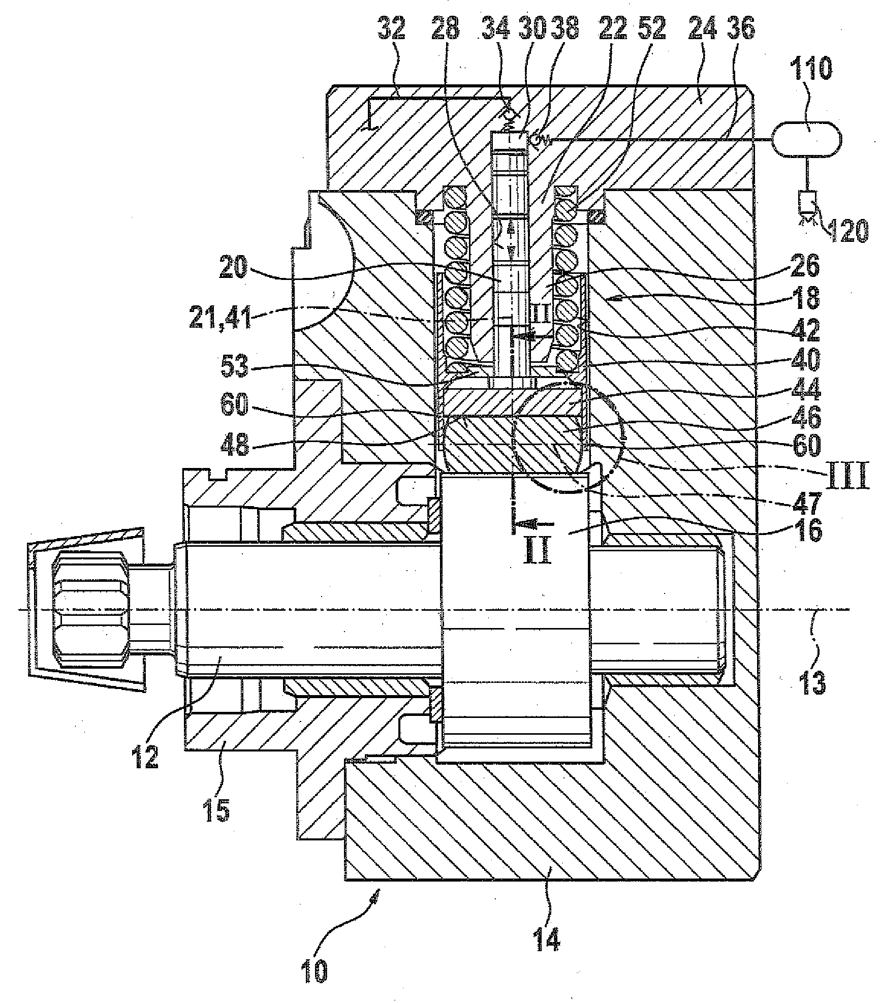
[0006]In FIG. 1 through 6, a high-pressure pump for a fuel injection system of an internal combustion engine is shown. The high-pressure pump has a multi-part pump housing 10, in which a drive shaft 12 driven to rotate by the engine is disposed. The drive shaft 12 is rotatably supported for instance via two bearing points, spaced apart from one another in the direction of the rotational axis 13 of the drive shaft 12. The bearing points can be disposed at various parts of the pump housing 10; for instance, a first bearing point can be disposed in a base body 14 of the pump housing 10, and a second bearing point can be disposed in a flange part 15 connected to the base body 14.

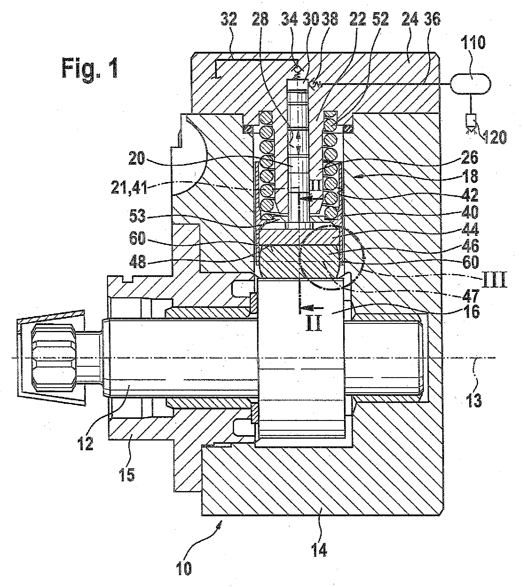
[0007]In a region located between the two bearing points, the drive shaft 12 has at least one cam 16 or portion embodied eccentrically to its rotational axis 13; the cam 16 can also be embodied as a multiple cam. The high-pressure pump has at least one or more pump elements 18, disposed in the housing 10, each h...


PUM


Abstract

The high pressure pump comprises a drive shaft (12) with at least one cam (16) or eccentric and at least one pump element (18) with a pump piston (20), driven in the reciprocating direction by the cam (16) or eccentric on the driveshaft (12) in a reciprocating motion. A support element (44) is arranged between the pump piston (20) and the cam (16) or eccentric on the driveshaft (12) and also a roller (46) running on the cam (16) or eccentric is mounted to rotate therein. A support (60) for the roller (46) in the direction of rotation is arranged adjacent to the same in the direction of the rotational axis (47) of the roller (46). The roller (46) and/or the support (60) comprises a surface with high wear resistance at least in the contact region between the roller (46) and the support (60).

Description

PRIOR ART[0001]The invention is based on a high-pressure pump, in particular for a fuel injection system of an internal combustion engine, as generically defined by the preamble to claim 1.[0002]One such high-pressure pump is known from German Patent Disclosure DE 199 07 311 A1. This high-pressure pump has a drive shaft with at least one cam or eccentric element. The high-pressure pump furthermore has at least one pump element, which has a pump piston that is driven in a reciprocating motion by the cam or eccentric element of the drive shaft. A support element is disposed between the pump piston and the cam or eccentric element, and a roller that rolls on the cam or eccentric element of the drive shaft is rotatably supported in the support element. It has been found that in operation of the high-pressure pump, forces acting in the direction of the rotational axis of the roller also act on the roller, and as the roller begins to roll on adjoining components, wear can occur on the rol...

Claims


Application Information

Patent Timeline
IPC IPC(8): F02M37/04
CPCF02M59/102F02M59/44F02M2200/02F04B1/0413F04B1/053F04B1/0531F05B2210/11Y10S415/00Y10S417/00
Inventor BAUER, PETERKOCH, MARKUSREPPHUN, GERNOTRITTMANNSBERGER, WOLFRAM
Owner ROBERT BOSCH GMBH
Why Eureka
Try Eureka