Synthetic Aperture focusing techniques

a synthetic aperture and radar technology, applied in the field of processing techniques, can solve the problems of adversely affecting the resulting image, unknown phase errors in imaging data, and inability to adapt to the resulting image,

Inactive Publication Date: 2008-12-04
THE BOARD OF TRUSTEES OF THE UNIV OF ILLINOIS
View PDF24 Cites 17 Cited by
  • Summary
  • Abstract
  • Description
  • Claims
  • Application Information

AI Technical Summary

Problems solved by technology

Unfortunately, standard SAR systems are susceptible to phase errors that can adversely impact a resulting image.
In synthetic aperture radar imaging, demodulation timing errors at the radar receiver due to signal delays resulting from inaccurate range measurements or signal propagation effects sometime produce unknown phase errors in the imaging data.
As ...

Method used


Image

  • Synthetic Aperture focusing techniques
  • Synthetic Aperture focusing techniques
  • Synthetic Aperture focusing techniques

Examples


experimental examples

[0050]The following experimental examples are provided for illustrative purposes and are not intended to limit scope of the inventions of the present application or otherwise be restrictive in character.

[0051]FIGS. 6-9 correspond to an experiment using an actual SAR image. To form a ground truth focused image, an entropy-minimization autofocus routine was applied to the given SAR image. FIG. 6 shows the resulting image, where the sinc-squared antenna footprint window of FIG. 7 was applied to each column to simulate the antenna footprint resulting from an unweighted antenna aperture. The cross-range FOV equals 95 percent of the main lobe width of the squared-sinc function, i.e., the image is cropped within the nulls of the antenna footprint, so that there is very large (but not infinite) attenuation at the edges of the image. FIG. 8 shows a defocused image produced by applying a white phase error function (i.e., independent phase components uniformly distributed between −π and π) to ...


PUM


Abstract

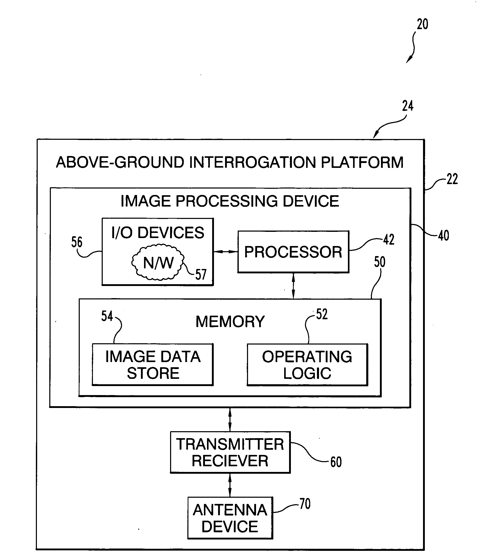
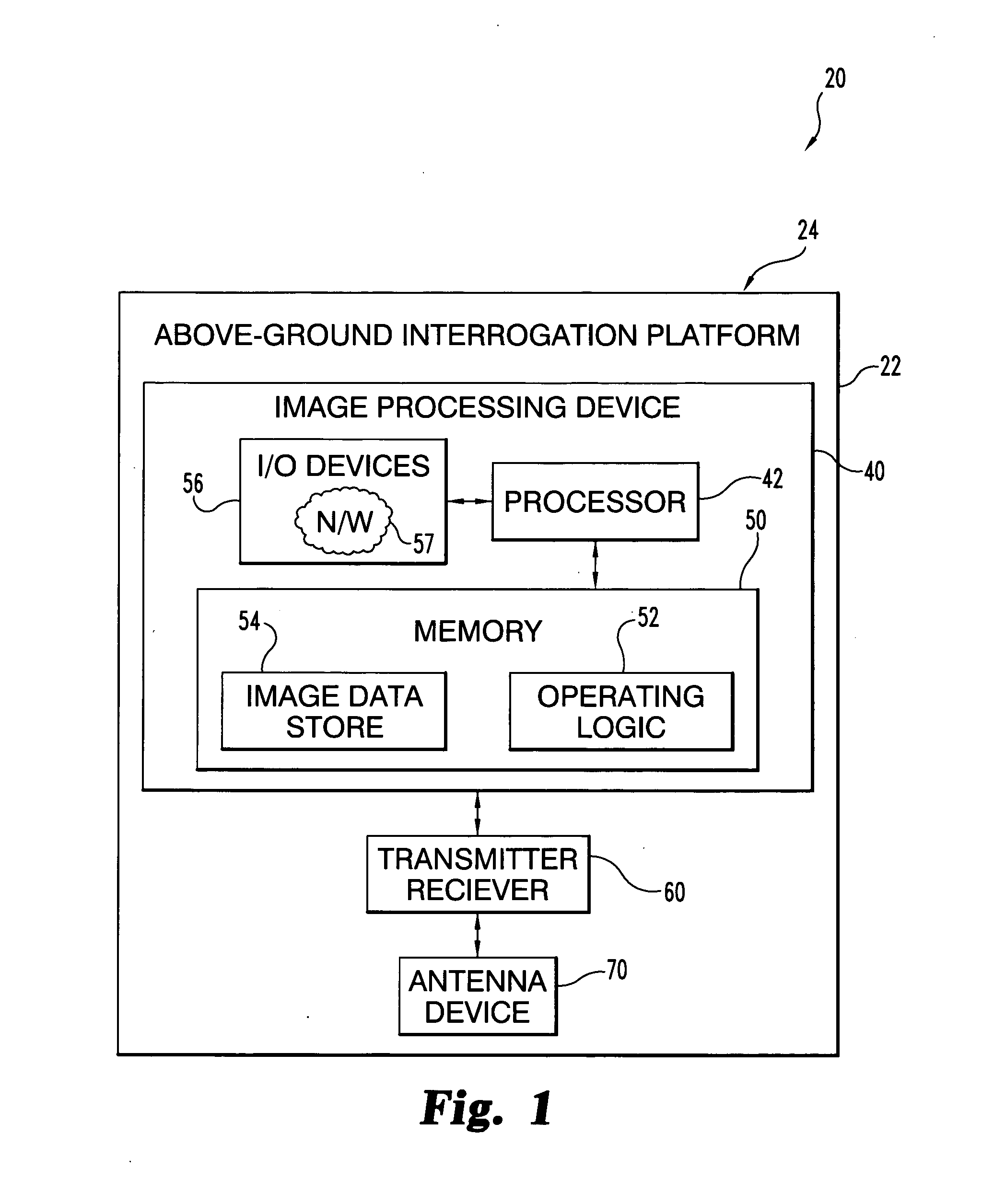
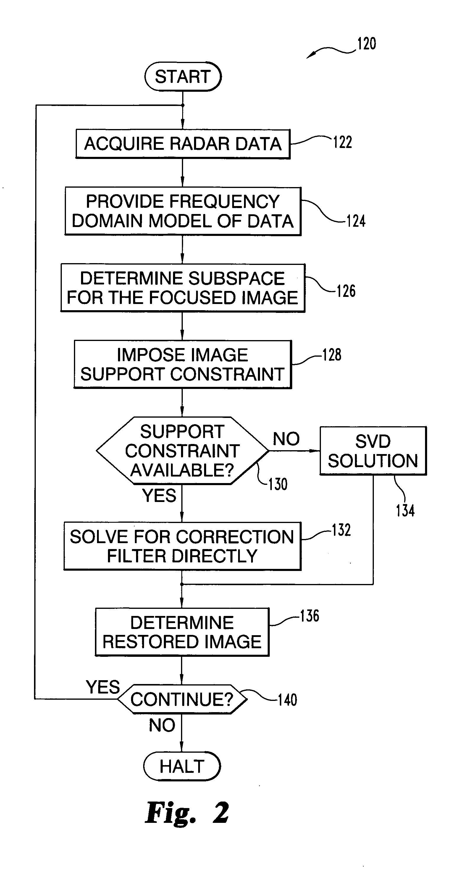
The present application describes an apparatus that includes a radar antenna device to acquire synthetic aperture radar data, radar receiver and transmitter equipment coupled to the radar antenna device, and a synthetic aperture radar processing device in communication with the radar receiver and transmitter equipment. This processing device includes a processor structured to process the synthetic aperture radar data, which is representative of a defocused image. The processor is further structured to define an image processing constraint corresponding to an image region expected to have a low radar return and generate one or more output signals as a function of the image processing constraint and the data. The one or more output signals are representative of a more focused form of the defocused image.

Description

CROSS-REFERENCE TO RELATED APPLICATIONS[0001]The present application claims the benefit of U.S. Provisional Patent Application No. 60 / 922,106, filed Apr. 6, 2007, which is hereby incorporated by reference herein.FEDERALLY SPONSORED RESEARCH OR DEVELOPMENT[0002]The present invention was made with Government assistance under National Science Foundation (NSF) Grant Contract Number CCR 0430877. The Government has certain rights in this invention.BACKGROUND[0003]The present invention relates to processing techniques, and more particularly, but not exclusively, relates to focusing synthetic aperture radar.[0004]Environmental monitoring, earth-resource mapping, and military systems are applications that frequently benefit from broad-area imaging at high resolutions. Sometimes such imagery is desired even when there is inclement weather or during night as well as day. Synthetic Aperture Radar (SAR) provides such a capability. SAR systems take advantage of the long-range propagation characte...

Claims


Application Information

Patent Timeline
IPC IPC(8): G01S13/90
CPCG01S13/90G01S13/9019
Inventor MORRISON, JR., ROBERT L.DO, MINH N.MUNSON, JR., DAVID C.
Owner THE BOARD OF TRUSTEES OF THE UNIV OF ILLINOIS
Why Eureka
Try Eureka