Head mounted display, display, and control method thereof

a display and display head technology, applied in the field of image display, can solve the problems of difficult to transmit the image, difficult to secure the user's sight, and frequent errors, and achieve the effect of simple and easy operation

Inactive Publication Date: 2008-12-04
CANON KK
View PDF3 Cites 44 Cited by
  • Summary
  • Abstract
  • Description
  • Claims
  • Application Information

AI Technical Summary

Benefits of technology

[0024]The present invention has been made in consideration of the above problems, and has as its object to provide a technique for, even if an error portion appears within an image of a certain frame, providing a suitable image by correcting the error portion in a simpler and easier way, when the image is presented to both eyes of an observer.

Problems solved by technology

In particular, when a wireless scheme is employed for image transmission, errors may occur frequently depending on the environment of use and the distance between the apparatuses.
However, the above-described prior art has the following problems.
Assume that an error occurs in wireless image transmission and it is difficult to transmit the image.
That is, it is difficult to secure the user's sight.
Furthermore, when an interpolation process is executed as in another conventional example, as the amount and frequency of error increase, it becomes difficult to reconstruct an image even if an identical image, stereoscopic image, or a preceding frame is used.
Therefore, it is also difficult to secure the wearer's sight.

Method used


Image

  • Head mounted display, display, and control method thereof
  • Head mounted display, display, and control method thereof
  • Head mounted display, display, and control method thereof

Examples


first embodiment

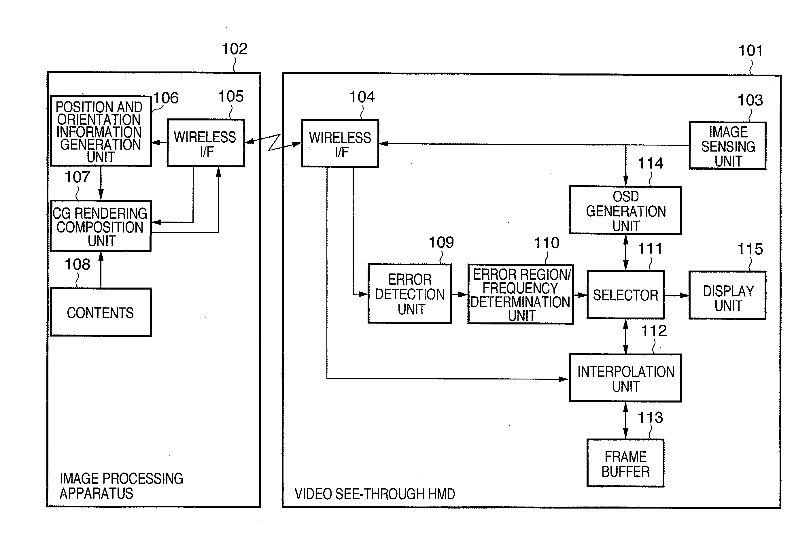
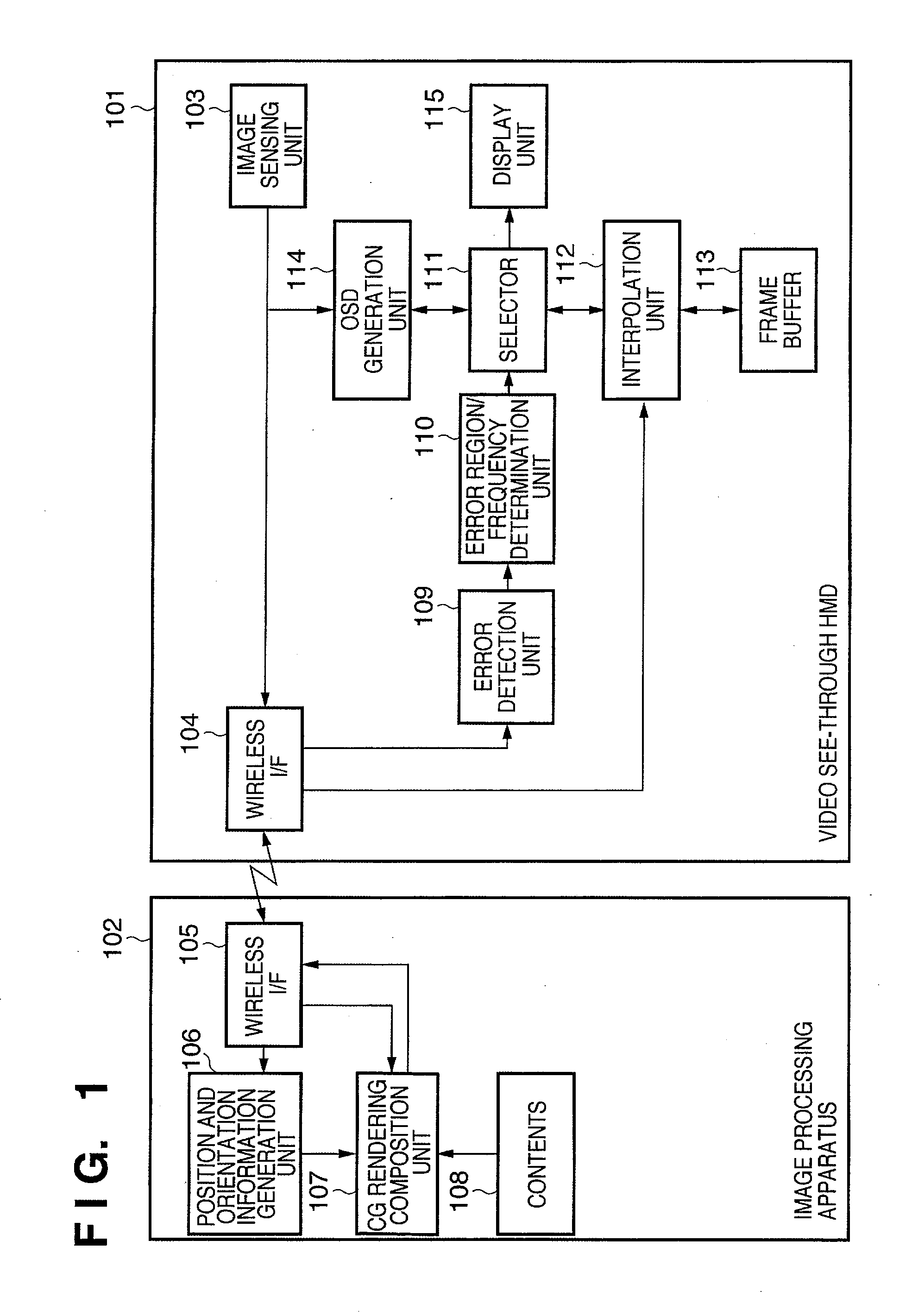
[0059]FIG. 1 is a block diagram showing the functional arrangement of a system according to this embodiment. As shown in FIG. 1, the system according to this embodiment comprises an image processing apparatus 102 represented by a computer such as a PC (Personal Computer), and a video see-through HMD 101 as an example of a head mounted display. The image processing apparatus 102 and the video see-through HMD 101 wirelessly communicate with each other.

[0060]The video see-through HMD 101 will be described first.

[0061]An image sensing unit 103 is attached at a position near an eye (either the left or right eye) of an observer wearing the video see-through HMD 101 on the head so as to face in a direction of line of sight of the observer. The image sensing unit 103 is a video camera (image sensing device) which senses a movie. Images (physical space images) of the sensed frames are sequentially output to a subsequent OSD (On Screen Display) generation unit 114 and wireless I / F 104. The wi...

second embodiment

[0106]In this embodiment, as an error portion correction method, a method of correcting an error portion by substituting an MR image generated for the other eye for an MR image of the frame of interest or a method of correcting the error portion by using a pixel group surrounding it is used.

[0107]FIG. 7 is a block diagram showing a functional arrangement example of a system according to this embodiment. As shown in FIG. 7, the system according to this embodiment comprises an image processing apparatus 702 and a video see-through HMD 701. The basic operation of the image processing apparatus 702 is the same as that of an image processing apparatus 102 shown in FIG. 1, and the different points from the first embodiment will be described below.

[0108]The video see-through HMD 701 will be described first. As shown in FIG. 7, the video see-through HMD 701 includes a presentation unit for presenting an image to the right eye of an observer wearing the video see-through HMD 701 on the head,...

third embodiment

[0144]FIG. 10 is a block diagram showing a functional arrangement example of a system according to this embodiment. As shown in FIG. 10, the system according to this embodiment comprises an image processing apparatus 1002 and a video see-through HMD 1001, which wirelessly communicate with each other. The system is the same as that in the first or second embodiment in this point.

[0145]The video see-through HMD 1001 will be described first.

[0146]A 3D position sensor 1005 is similar to the 3D position sensor 704 shown in FIG. 7. The 3D position sensor 1005 measures the position and orientation of itself, and outputs the measurement result as position and orientation information to a subsequent position and orientation information generation unit 1006.

[0147]The position and orientation information generation unit 1006 calculates the position and orientation of an image sensing unit 1003 by adding the position and orientation relationship between the 3D position sensor 1005 and the image...


PUM


Abstract

If the size of an error portion within an image of the frame of interest is equal to or larger than a threshold and it is determined that no error portion exists within an image of a frame immediately before the frame of interest, a display unit (115) is caused to display the image of the frame immediately before the frame of interest as the image of the frame of interest. If the size of an error portion within the image of the frame of interest is smaller than the threshold and it is determined that an error portion exists within the image of the frame immediately before the frame of interest, the display unit (115) is caused to display a result obtained by correcting the error portion within the image of the frame of interest using a pixel group surrounding the error portion.

Description

BACKGROUND OF THE INVENTION[0001]1. Field of the Invention[0002]The present invention relates to a technique of displaying an image.[0003]2. Description of the Related Art[0004]Mixed reality, that is, so-called MR is recently known as a technology of merging a real world and a virtual world seamlessly in real time. In one MR technology, a video see-through HMD (Head Mounted Display) is used and an object almost matching an object observed from the pupil position of an HMD wearer is sensed by, for example, a video camera. A CG (Computer Graphics) image is superimposed on the sensed image to generate an image. The generated image is presented in front of the eyes of the HMD wearer.[0005]FIG. 12 is a block diagram showing the functional arrangement of a general video see-through mixed reality system (to be referred to as a system hereinafter). A general system will be described below with reference to FIG. 12.[0006]As shown in FIG. 12, the system comprises an image processing apparatus...

Claims


Application Information

Patent Timeline
Patent Type & Authority Applications(United States)
IPC IPC(8): G09G5/00H04N19/00H04N19/102H04N19/134H04N19/182H04N19/196H04N19/44H04N19/59H04N19/597H04N19/895H04N21/41H04N21/4425H04N21/854
CPCG02B27/017G02B2027/014G02B2027/0187G09G5/006G09G5/363G06T19/006G09G2340/125G09G2360/18G09G2370/16G09G2380/02G02B27/0101G09G5/393
Inventor OIKAWA, MAKOTOSUZUKI, MASAHIROSHIMOYAMA, TOMOHIKOKATAYAMA, AKIHIRO
Owner CANON KK
Why Eureka
Try Eureka