High Precision Feed Particularly Useful for UV Ink Jet Printing on Vinyl

a high-precision, vinyl-based technology, applied in the direction of printing, typewriters, other printing apparatus, etc., can solve the problems of limiting the resolution of the image being printed and the overall quality of the image, uv-curable inks without some of the disadvantages of occupational and environmental hazards, and low-absorption substrates, etc., to achieve the effect of increasing precision

Inactive Publication Date: 2008-12-04
POLYTYPEAG
View PDF12 Cites 3 Cited by
  • Summary
  • Abstract
  • Description
  • Claims
  • Application Information

AI Technical Summary

Benefits of technology

[0010]A primary objective of the present invention is to provide for increased precision in the imparting of relative movement of a substrate relative to the transverse path of an ink-jet printhead.

Problems solved by technology

This dot spread, however, limits the resolution of the image being printed and the overall quality of the image.
Advantages in wide format ink jet printing have resulted from the use of inks that are cured by exposure to ultraviolet light.
Furthermore, UV-curable inks do not have some of the occupational and environmental disadvantages of some other inks.
Higher resolution can, however, reveal artifacts such as those caused by feed or indexing tolerances between scan rows of the printhead.
This has created problems with roll-fed substrates, particularly smooth, low-absorbency substrates, that can occur when the dot-spread is minimal.
Web fed printers are particularly prone to longitudinal feed errors that have been difficult to control.
Cumulative tolerances in the drive linkages, potential slippage of the substrate on the rollers, and other mechanical limitations have produced errors that are difficult to predict when attempting to longitudinally index a web, particularly a web of highly flexible material.
The use of an encoder in a closed loop control of the substrate feed drive has been only moderately successful because of a lack of control “stiffness” in the loop.
The use of an encoder to read the results of an indexing step and feed the results back to the control to make a subsequent correction has presented other problems.
When error signals from encoders have been received by feed system controllers following a longitudinal feed step, time is consumed in making a post-feed correction, delaying the transverse printhead scan.
Further, the correction feed step is also prone to error, which can require a still further corrective move.
In addition, the error can indicate that the substrate has been fed too far, requiring a negative correction step, or a backward move of the web.
Not all machines are capable of executing reverse moves of a substrate web, and many of those that can reverse the substrate feed cannot do so accurately or efficiently.
As a result, deliberately under-feeding the web has been tried.
Underfeeding of the web increases the likelihood that a correction is needed and increases the overall likely number of corrections that must be made.
As a result of these difficulties, high quality ink-jet printing with UV ink onto smooth substrates has not been realized in most applications where the above problems are presented.

Method used


Image

  • High Precision Feed Particularly Useful for UV Ink Jet Printing on Vinyl
  • High Precision Feed Particularly Useful for UV Ink Jet Printing on Vinyl
  • High Precision Feed Particularly Useful for UV Ink Jet Printing on Vinyl

Examples


Embodiment Construction

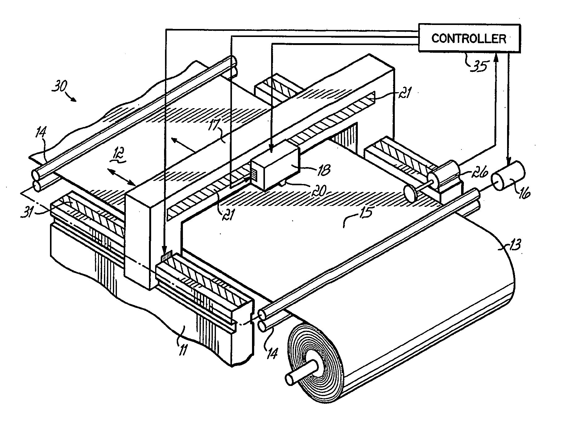
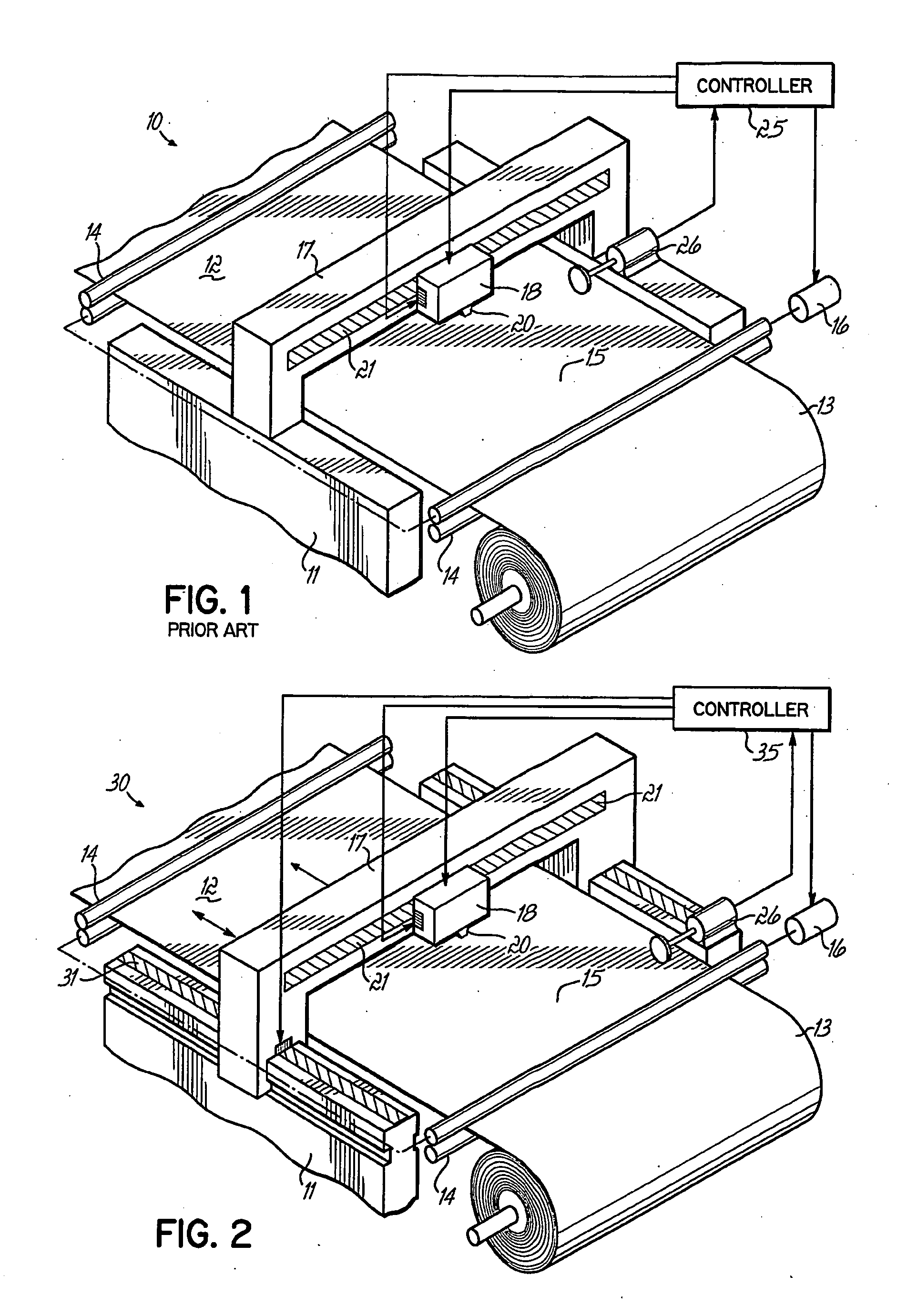
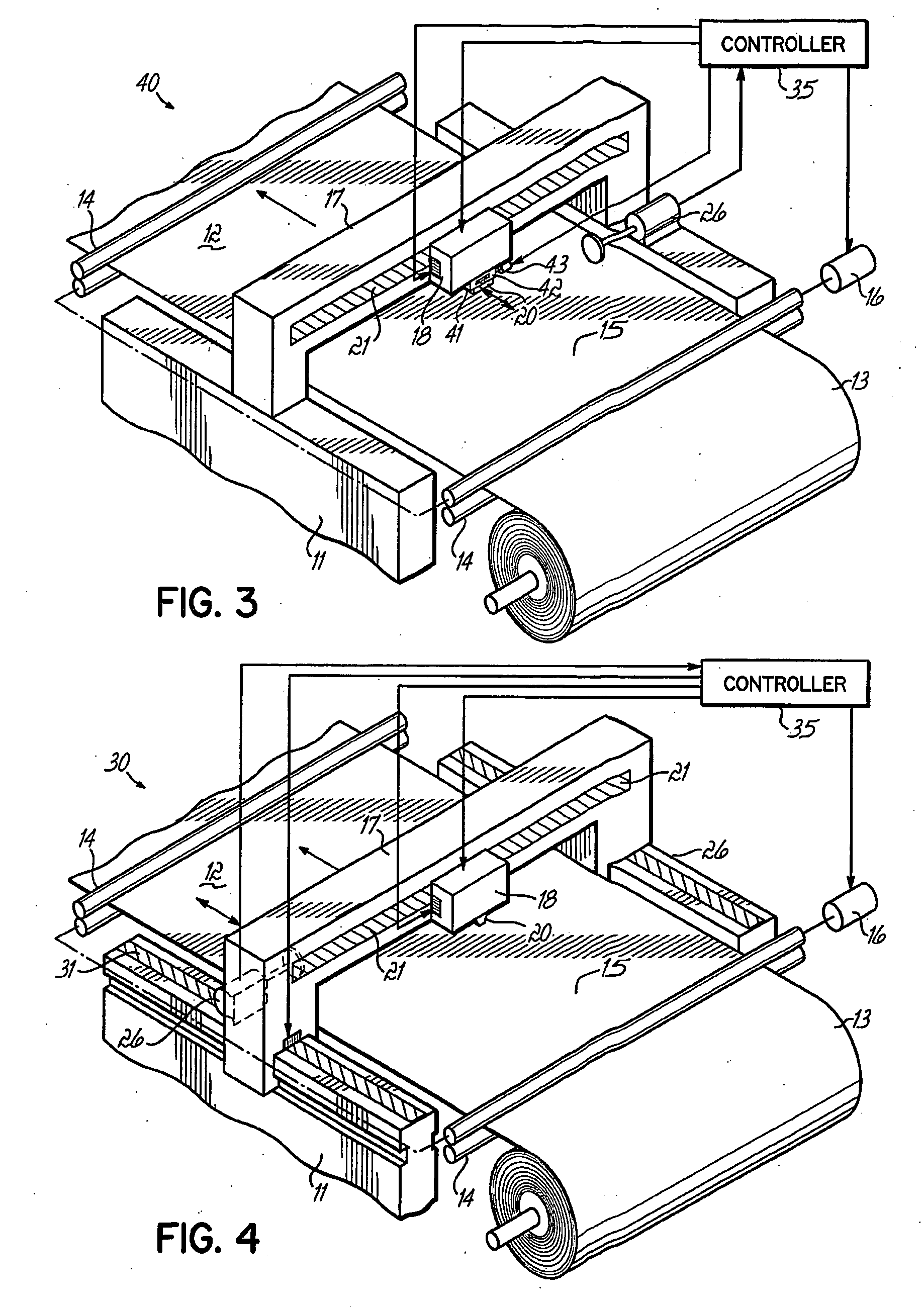
[0017]In FIG. 1, an ink-jet printing apparatus 10 of the prior art is illustrated. The apparatus 10 includes a frame 11 having a substrate support plane 12 over which a substrate 15 is supported. The substrate 15 is illustrated as a web of material that is longitudinally fed from a roll supply 13 thereof, along the frame 11 and over the support plane 12, by one or more sets of feed rolls 14 that are mounted to rotate on the frame 11. A drive motor 16, which may be a servo drive motor, advances the substrate 15 past a bridge 17, which is fixed to the frame 11, and on which bridge is mounted a carriage 18 to move on the bridge 17 in a direction transverse to that of the feed. The carriage 18 has mounted thereon one or more ink-jet printheads 20, which it carries with it transversely across the frame 11. The carriage 18 is moved across the bridge 17 by a linear servo motor 19 carried by the bridge 17 and the carriage 18. The printheads 20 include nozzles (not shown), which are directed...


PUM


Abstract

An apparatus (30, 40, 50) and a method of ink jet printing arc disclosed that use a system for feeding a substrate longitudinally relative to a support area and a system for moving a printhead parallel to the direction of substrate feed. Indexing between transverse scan rows of a printhead (20) is carried out initially by the substrate feed system (16) and the actual feed distance is measured using an encoder or other substrate position measurement device (26). A controller (25) determines the amount of any error that occurs between the actual and the desired feed distances. The controller (25) then sends signals to move the printhead (20) to compensate for any error in the feed system feed. Compensating adjustments are then made to the next subsequent substrate indexing step so that the printhead tends to move back toward its home or zeroed position with its next correction and does not walk away from this home position as a result of cumulative movements. For printers that have bridges (17) moveable relative to the machine frame (11) on which the printhead (20) is carried, printhead motion is achieved by moving the bridge, for example, by actuating a linear servo bridge motion system (31). For fixed bridge roll-to-roll printers, the printhead (20) can be caused to shift longitudinally on the bridge (17) to make the correcting movements.

Description

[0001]This application claims the benefit of U.S. Provisional Application Ser. No. 60 / 540,933, filed Jan. 30, 2004, hereby expressly incorporated herein by reference.FIELD OF THE INVENTION [0002]This invention relates to ink jet printing, and more particularly, to the longitudinal indexing of a printhead relative to a substrate between transverse scans of the printhead.BACKGROUND OF THE INVENTION[0003]The use of ink jet printing in wide format applications is expanding. In wide-format ink-jet printing, substrates, from rigid panels or flexible roll-to-roll webs, are supported relative to an ink-jet printhead. The printhead typically prints by moving transversely, relative to the substrate at a printing station where the substrate is supported, to print a row of an image on the substrate. The printhead moves across the substrate on a bridge that extends transversely across the substrate at the printing station, carrying the printhead on a carriage that is moveable on the bridge. Such...

Claims


Application Information

Patent Timeline
Patent Type & Authority Applications(United States)
IPC IPC(8): B41J23/00B41J3/28B41J11/00B41J11/42B41J15/04
CPCB41J3/28B41J11/001B41J11/002B41J11/42B41J15/04B41J11/00
Inventor CODOS, RICHARD N.COLLAN, WILLIAM W.QUATTROCIOCCHI, ANGELOVOGEL, PETER
Owner POLYTYPEAG
Why Eureka
Try Eureka