Method and Apparatus For Computer Network Bandwidth Control and Congestion Management

a computer network and bandwidth control technology, applied in the field of protocols and mechanisms for congestion management in the layer 2 computer network, can solve the problems of re-calculation of packet checksums, computer network congestion, and slower reaction tim

Inactive Publication Date: 2008-12-04
TEAK TECH
View PDF8 Cites 172 Cited by
  • Summary
  • Abstract
  • Description
  • Claims
  • Application Information

AI Technical Summary

Benefits of technology

[0014]In one embodiment, a network switch includes first logic for receiving a flow, including identifying a reaction point as the source of the data frames included in the flow. The network switch further includes second logic for detecting congestion at the network switch and associating the congestion with the flow and the reaction point, third logic for generating congestion notification information in response to congestion, and fourth logic for receiving control information, including identifying the reaction point as the source of the control information. The network switch further includes fifth logic for addressing the congestion notification information and the control information to the reaction point, wherein the data rate of the flow is based on the congestion notification information and the control information. The content of the data frames included in the flow is independent of the congestion notification information and the control information in a first mode of the network switch.
[0015]In another embodiment, a network switch includes first logic for receiving congestion notification information associated with a congestion point and a flow. The network switch generates the flow, and the congestion notification information is addressed to the network switch. The network switch further includes second logic f

Problems solved by technology

As a result of increasing data traffic, a computer network can sometimes experience congestion.
Some protocols may require in-flow packet modification and, thus, re-calculation of packet checksums, which is typically undesirable in a Layer 2 switch.
A specific disadvantage of forward notification protocols is that their reaction time will typically be slower than backward notification protocols, since congestion-related control packets often have to travel a greater distance and number of hops through the Layer 2 network.
Also, any network bottlenecks may result in loss of congestion-related control packets, which in turn can cause protocol failures.
While this can also occur with backward notification protocols, the probability of congestion-related control packet loss is typically higher with forward notification protocols.
In addition, these protocols make a congestion management coprocessor implementation difficult, if not impossible, since these protocols generally act upon and possibly modify packets in the data path.
The above-described disadvantages of tagging protocols can be at least partially offset by the creation of an implicit closed control loop in such protocols.
Because data packets are not tagged in non-tagging protocols, this mechanism is typically not available in non-tagging protocols.
While relatively simple to implement, this protocol may recover available bandwidth very slowly and/or after a relatively long period of time.
In some situations, such as under transient congestion conditions caused by bursty traffic, the use of this

Method used


Image

  • Method and Apparatus For Computer Network Bandwidth Control and Congestion Management
  • Method and Apparatus For Computer Network Bandwidth Control and Congestion Management
  • Method and Apparatus For Computer Network Bandwidth Control and Congestion Management

Examples


Embodiment Construction

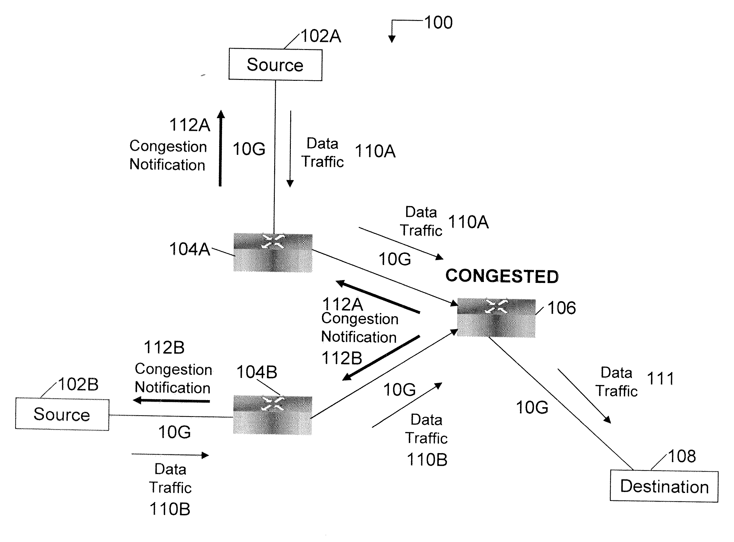
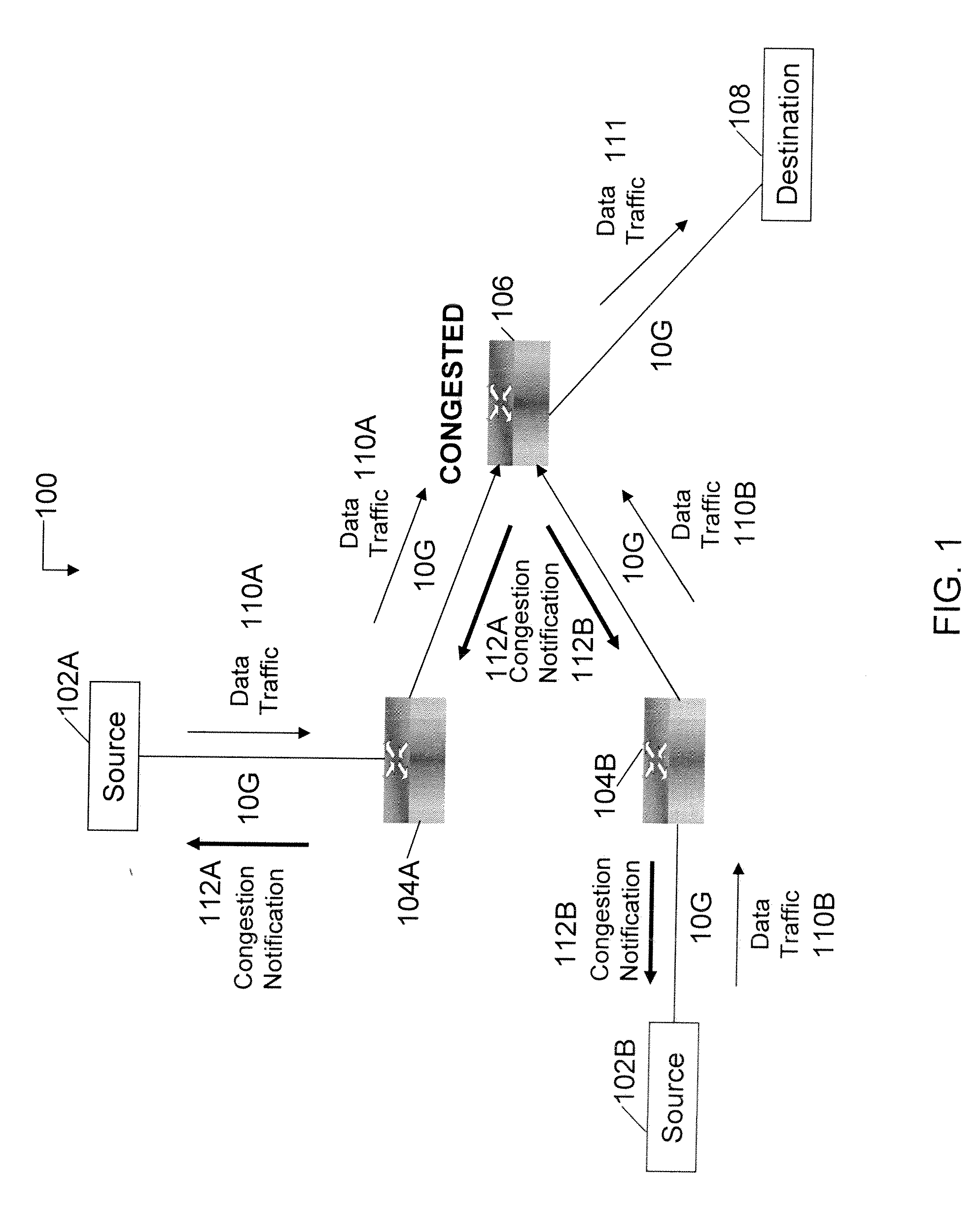
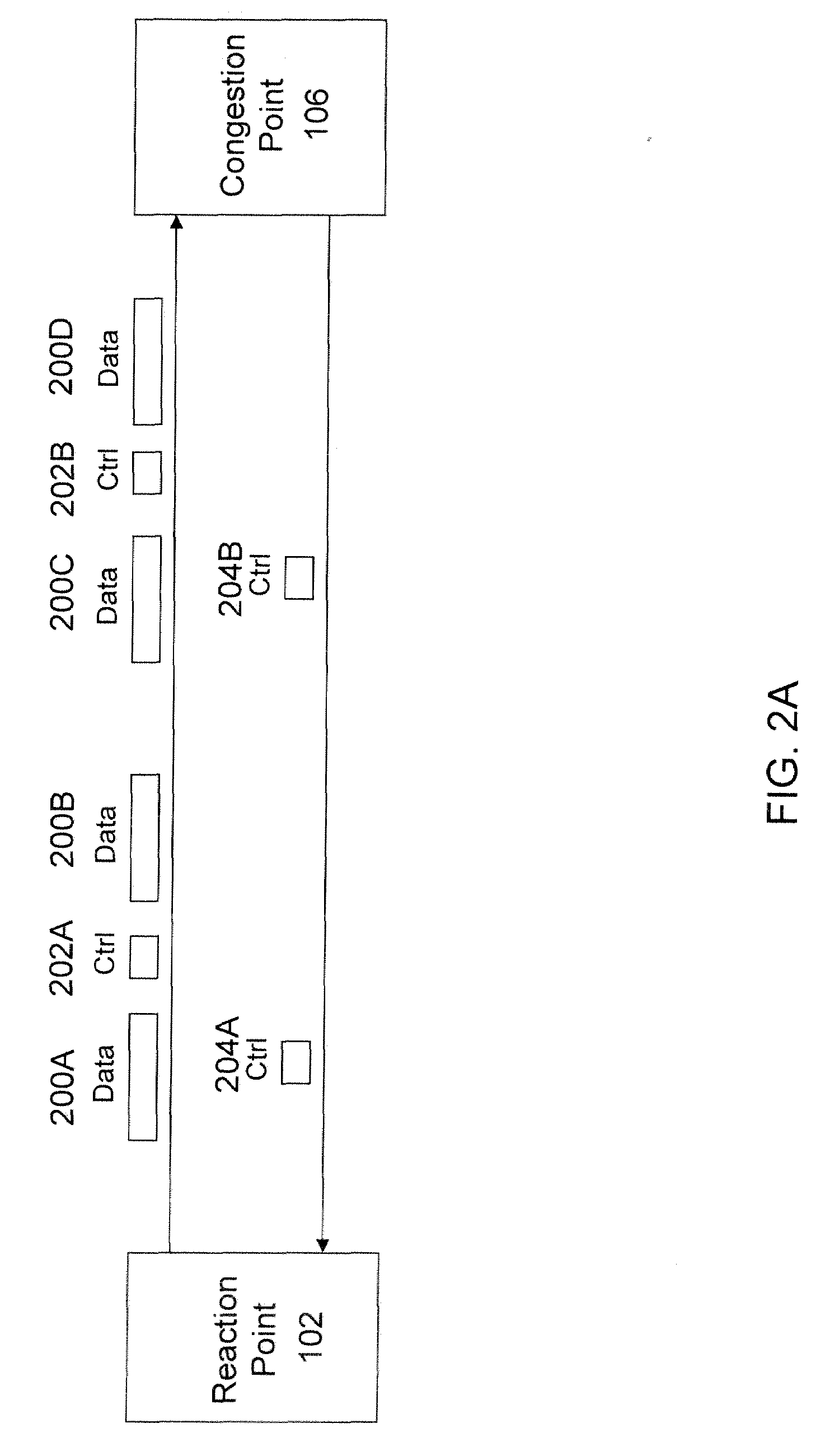
[0026]One embodiment of the invention provides a protocol to implement congestion management in a Layer 2 computer network, such as Ethernet. Described herein are a congestion management protocol and a congestion management module.

[0027]Embodiments of the protocol to implement congestion management may support both tagging and non-tagging operation, backward notification for signaling, adjustment of data rates of flows that is responsive to RTT between a reaction point and a congestion point, positive feedback to increase the data rate as well as negative feedback to reduce the data rate, congestion point based data rate calculations and adjustments, and variable sampling rates when monitoring for congestion at a congestion point.

[0028]Another embodiment of the invention provides an apparatus and method to implement congestion management in a Layer 2 switch, such as using a coprocessor device that operates in conjunction with a switch core chip. Described herein are switch chip spec...


PUM


Abstract

In one embodiment, a network switch includes first logic for receiving a flow, including identifying a reaction point as the source of the data frames included in the flow. The network switch further includes second logic for detecting congestion at the network switch and associating the congestion with the flow and the reaction point, third logic for generating congestion notification information in response to congestion, and fourth logic for receiving control information, including identifying the reaction point as the source of the control information. The network switch further includes fifth logic for addressing the congestion notification information and the control information to the reaction point, wherein the data rate of the flow is based on the congestion notification information and the control information. The content of the data frames included in the flow is independent of the congestion notification information and the control information in a first mode of the network switch.

Description

CROSS REFERENCES TO RELATED APPLICATIONS[0001]The present application claims the benefit of the following commonly owned U.S. provisional patent applications, all of which are incorporated herein by reference in their entirety: (1) U.S. Provisional Patent Application No. 60 / 940,433, Attorney Docket No. TEAK-012 / 00US, entitled “Method and Apparatus for Computer Network Congestion Management,” filed on May 28, 2007; (2) U.S. Provisional Patent Application No. 60 / 950,034, Attorney Docket No. TEAK-011 / 00US, entitled “Method and Apparatus for Computer Network Congestion Management with Improved Data Rate Adjustment,” filed on Jul. 16, 2007; and (3) U.S. Provisional Patent Application No. 60 / 951,639, Attorney Docket No. TEAK-012 / 00US, entitled “Method and Apparatus for Computer Network Congestion Management with Determination of Congestion at Variable Intervals,” filed on Jul. 24, 2007.FIELD OF THE INVENTION[0002]The invention generally relates to the field of protocols and mechanisms for...

Claims


Application Information

Patent Timeline
IPC IPC(8): H04L12/56
CPCH04L47/10H04L47/11H04L47/263H04L49/505
Inventor ROECK, GUENTERLIU, HUMPHREY
Owner TEAK TECH
Why Eureka
Try Eureka