Particle-Beam Treatment System

a treatment system and particle beam technology, applied in the field of particle beam treatment system, can solve the problems of difficult to securely monitor the body position that is subject to irradiation, difficult to provide additional reinforcement, etc., and achieve the effect of avoiding inappropriate particle beam irradiation

Active Publication Date: 2008-12-04
MITSUBISHI ELECTRIC CORP
View PDF7 Cites 34 Cited by
  • Summary
  • Abstract
  • Description
  • Claims
  • Application Information

AI Technical Summary

Benefits of technology

[0023]According to a particle-beam treatment system of the present invention, an image of the video camera that shoots the multileaf-collimator shape reflected by the shape-monitoring mirror and multileaf-collimator-shape information in a treatment plan are compared, and particle-beam irradiation or particle-beam cutoff processing is performed depending on whether or not the comparison result is appropriate; therefore, inappropriate particle-beam irradiation can be avoided.

Problems solved by technology

Moreover, because the space above the monitor drive stand 51 is limited, it is difficult to provide additional reinforcement.
It is possible in principle to make the leaf-position detector 25 multiple and redundantly ascertain the shape 21 of the multileaf collimator, in order to ascertain the setting condition during particle-beam irradiation; however, the multileaf collimator has a great number of drive elements and the space where the newly added leaf-position detectors and signal transmission paths are mounted in the multileaf collimator head unit is limited, whereby many difficult issues exist.
In the conventional monitoring through the video camera 15 disposed on the sidewall or the ceiling of a treatment room, a dead angle or the like, which may be caused depending on the irradiation arrangement, may make it difficult to securely monitor the body position that is subject to irradiation.

Method used


Image

  • Particle-Beam Treatment System
  • Particle-Beam Treatment System
  • Particle-Beam Treatment System

Examples


embodiment 1

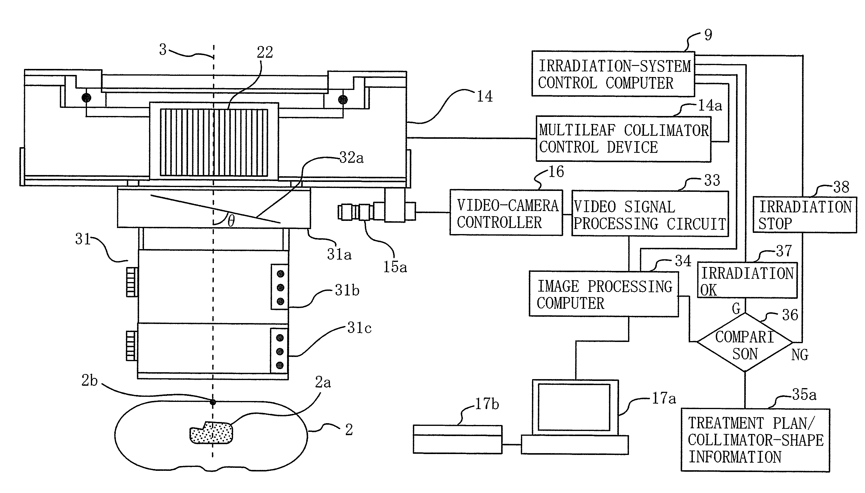
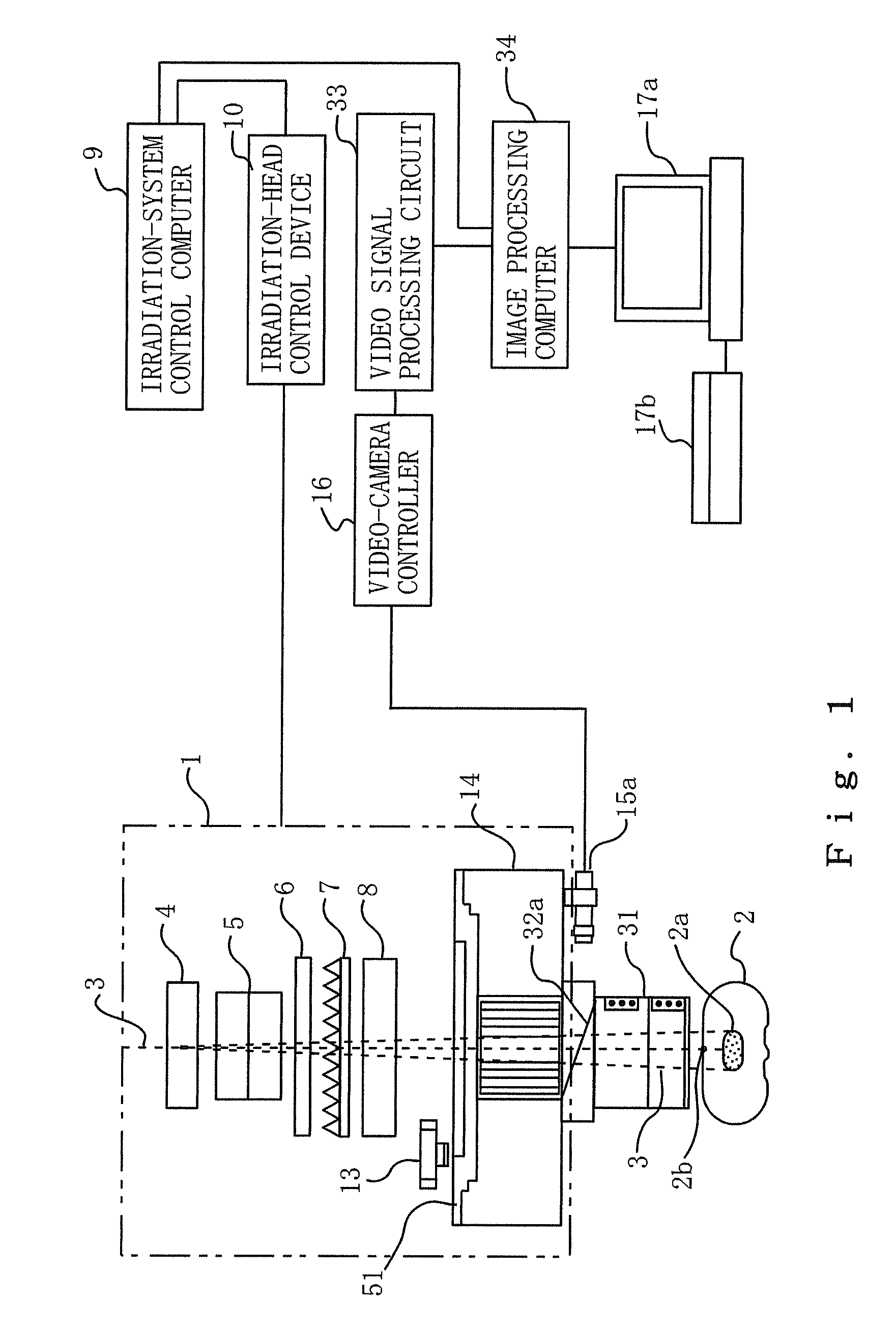
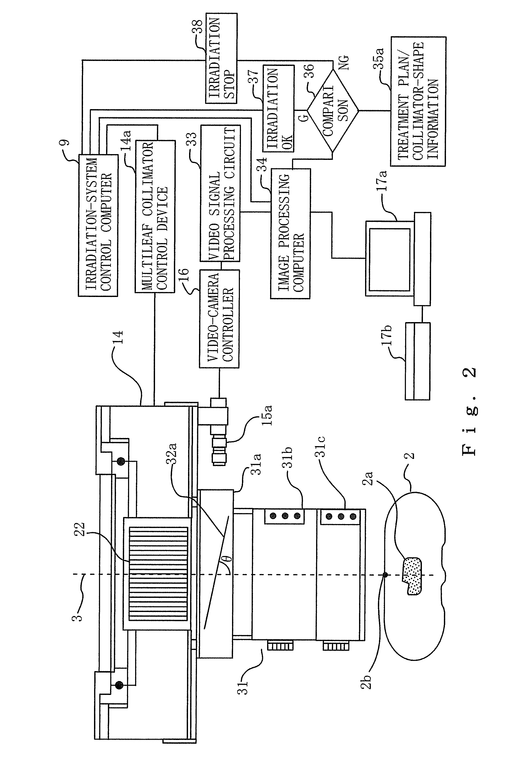
[0034]FIG. 1 is a system block diagram illustrating a particle-beam treatment system according to Embodiment 1 of the present invention. FIG. 1 illustrates principle constituent elements in a configuration in which an optical shape-monitoring unit, which includes a multileaf-collimator-shape monitoring mirror utilized in the multi-layer conformal irradiation, is mounted in an irradiation head. FIG. 2 is a system block diagram illustrating a multileaf collimator head unit and the control system therefor according to Embodiment 1. FIG. 3 is a flowchart representing a collimator-shape monitoring flow according to Embodiment 1. Meanwhile, the structure and the leaf-position detection mechanism of the typical multileaf collimator explained with reference to FIG. 9 can directly be applied to Embodiment 1; in the present specification, the same reference characters in the figures denote identical or corresponding parts; therefore, explanations therefor may be omitted.

[0035]In FIG. 1, refer...

embodiment 2

[0044]In Embodiment 1, the shape of a multileaf collimator is shot by means of the shape-monitoring mirror 32a, and the video camera 15a; however, the monitoring of a patient position, which is symmetric with the multileaf collimator 14 with respect to the mirror plane, can be performed with a similar shooting system. In other words, by making the monitoring mirror a two-side mirror and utilizing the respective sides as the shape-monitoring mirror 32a and a patient-position monitoring mirror 32b, the multileaf-collimator shape and the patient position can be monitored and ascertained concurrently or in a time-division fashion. FIG. 4 is a system block diagram illustrating a multileaf collimator head unit and the control system therefor according to Embodiment 2.

[0045]FIG. 5 is a flowchart representing a patient-position monitoring flow according to Embodiment 2; In Embodiment 2, the steps in the flowchart, in FIG. 3, representing a collimator-shape monitoring flow are performed conc...

embodiment 3

[0054]FIG. 6 is a system block diagram illustrating a multileaf collimator head unit and the control system therefor according to Embodiment 3. In the case where a compensation filter (for compensating the particle-beam distribution) is mounted in the compensation filter mounting stand 31b of the optical shape-monitoring unit 31, or in the case where a patient collimator is mounted in the patient collimator mounting stand 31c, it is impossible or difficult, with Embodiment 2, to monitor and ascertain the patient position. In order to solve the foregoing problem, a patient-position monitoring mirror mounting stand 31d on which the patient-position monitoring mirror 32 is disposed is mounted on the front end of the optical shape-monitoring unit 31 so as to monitor and ascertain the patient position. In this case, the patient-position monitoring mirror 32c and the patient-position monitoring mirror mounting stand 31d configure an optical patient-position monitoring unit; i.e., the opti...


PUM


Abstract

Provision is made for a particle-beam treatment system in which, even during particle-beam irradiation, the shape of a multileaf collimator is monitored. The particle-beam treatment system, in which multi-layer conformal irradiation is performed while the setting of the shape of the multileaf collimator in an irradiation head is changed during particle-beam irradiation, is provided with an optical shape-monitoring unit mounted attachably and detachably in the snout portion at the downstream side of the multileaf collimator, the optical shape-monitoring unit having a shape-monitoring mirror, opposing the multileaf collimator, for monitoring the shape of the multileaf collimator; a video camera for shooting the multileaf-collimator shape reflected by the shape-monitoring mirror; and an image monitor for displaying an image of the video camera that shoots the shape of the multileaf collimator.

Description

BACKGROUND OF THE INVENTION[0001]1. Field of the Invention[0002]The present invention relates to a particle-beam treatment system in which, in the case where, during particle-beam irradiation, multi-layer conformal irradiation is performed while setting of the shape (leaf position) of a multileaf collimator in an irradiation head is changed, the shape of the multileaf collimator is detected by a leaf-position detection mechanism, and more particularly to a particle-beam treatment system in which, during particle-beam irradiation, the shape of the multileaf collimator can be monitored.[0003]2. Description of the Related Art[0004]In a particle-beam treatment system that performs multi-layer conformal irradiation, the dose to be administered to a patient and the distribution thereof are spatially divided and then delivered, so that the dose delivery is made optimal for the shape of a target. The dose distribution divided and delivered in this manner depends on the setting of the irradi...

Claims


Application Information

Patent Timeline
Patent Type & Authority Applications(United States)
IPC IPC(8): G21K5/04
CPCA61B5/1127A61N5/1042A61N5/1064A61N2005/1059A61N2005/1087G21K1/046
Inventor TAKAHASHI, OSAMUPU, YUEHUHARADA, HISASHIIKEDA, MASAHIROTAKATANI, YASUYUKIOTANI, HIROSHI
Owner MITSUBISHI ELECTRIC CORP
Why Eureka
Try Eureka