Battery pack

a battery pack and battery technology, applied in the field of batteries, can solve the problems of shortening the life of the battery pack, unable to meet the requirements of 20 years, etc., and achieve the effect of reducing the risk of damag

Inactive Publication Date: 2008-12-04
TDK LAMBDA CORP
View PDF1 Cites 32 Cited by
  • Summary
  • Abstract
  • Description
  • Claims
  • Application Information

AI Technical Summary

Benefits of technology

[0019]Accordingly, since a heat dissipating area increases by the heat dissipating members to dissipate rapidly heat generated in each battery bodies building up the battery pack and each the heat dissipating member is thermally connected with each other by the heat transfer members. Accordingly, heat of each battery body is equalized to make a life span of each battery cell substantially approximate to each other to prevent the battery bodies, eventually the whole of the battery pack from shortening in life span, thus permitting the life span of the whole of the battery pack to lengthen.
[0020]According to the first aspect of the present invention, the surface pressure of each battery cell is allowed to be equalized, thus permitting the whole of the battery pack to lengthen in life span.
[0021]According to the second a

Problems solved by technology

There has been, however, the problem that in the existing battery pack, a plurality of the battery cells 21 is stacked to form the battery pack 20 and thereby when each battery cell 21 generates heat in charging or dischargin

Method used


Image

  • Battery pack
  • Battery pack
  • Battery pack

Examples


Embodiment Construction

[0030]The following is a detailed description of preferred embodiments of a battery pack according to the present invention with reference to the appended drawings. In addition, the same numeral symbols are labeled for parts the same as in a conventional example and descriptions of common parts are omitted to avoid overlap in the description.

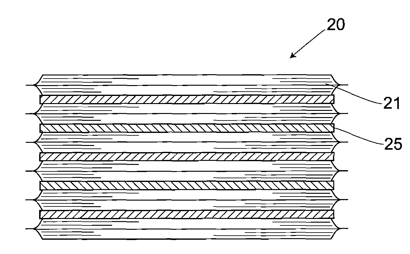
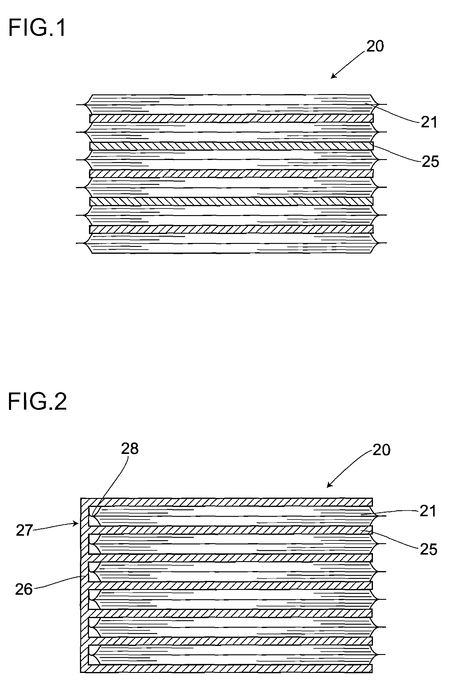
[0031]FIG. 1 is a longitudinal cross-sectional view of a substantial part, representing a configuration of the battery pack in a first embodiment. As a battery cell 21 acting as a battery body building up a battery pack 20, the same lithium-ion battery as shown in the conventional example is employed. More specifically, an inside of the battery cell 21 is e.g., so structured that each of positive and negative electrode plates and each of separators are stacked in some layers and then the stacked layers together with an electrolyte are sealed by an aluminum laminate or the like. In the present embodiment, the battery pack 20 is built by stacking ...


PUM


Abstract

The battery pack is made up by stacking vertically a plurality of electrically-series-connected flat-plate-like battery cells so as to attain a given voltage and a given capacity. Interlayer members are interposed between each battery cell stacked. The interlayer member functions as a surface pressure distributing member to thereby equalize surface pressures of the battery cells building up the battery pack, thus permitting the whole of the battery pack to lengthen in life span. Further, by employing, as the interlayer members, heat insulating members with heat insulating efficiency or heat dissipating members with excellent thermal conductivity, the battery cell located in a central position of the battery pack is prevented from shortening partially in life span, thus permitting the whole of the battery pack to lengthen in life span.

Description

CROSS-REFERENCE TO RELATED APPLICATION[0001]The present application is related to Japanese Patent Application No. 2005-004392, filed Jan. 11, 2005. The content of the application is incorporated herein by reference in its entirety.FIELD OF THE INVENTION[0002]The present invention relates to a battery pack such as that of lithium-ion batteries made available for an electric source utilized for a wide variety of electronic equipment.BACKGROUND OF THE INVENTION[0003]In general, in an uninterruptible electric power unit requiring a backup electric source, when an input voltage from a commercial alternating current source is being normally generated, necessary direct-current or alternating voltage is supplied from a main electric source of an electric source body acting as electronic equipment to a load with a secondary battery being charged via the main electric source. On the one hand, when the input voltage has dropped markedly or electric power interruption has occurred, a secondary ...

Claims


Application Information

Patent Timeline
IPC IPC(8): H01M6/46
CPCH01M2/1094H01M10/0481H01M10/0525H01M10/5008H01M10/5032H01M10/5055H01M10/5087Y02E60/122H01M10/647H01M10/6555H01M10/617H01M10/658Y02E60/10H01M50/24
Inventor NAKAZAWA, HIROSHI
Owner TDK LAMBDA CORP
Why Eureka
Try Eureka