
Chemical Liquid Injection System

Inactive Publication Date: 2008-12-04
NEMOTO KYORINDO KK
View PDF7 Cites 9 Cited by
  • Summary
  • Abstract
  • Description
  • Claims
  • Application Information

AI Technical Summary

Benefits of technology

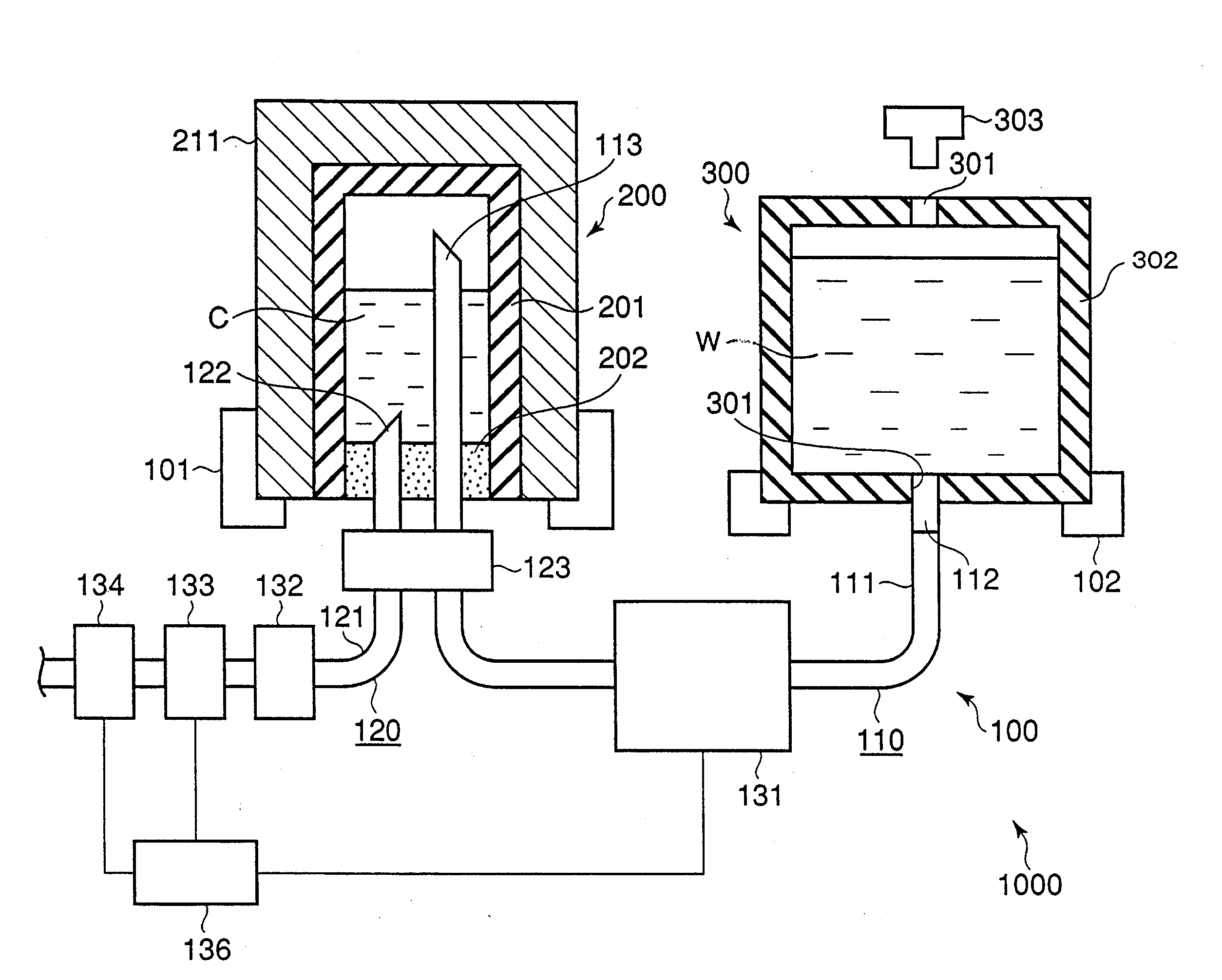
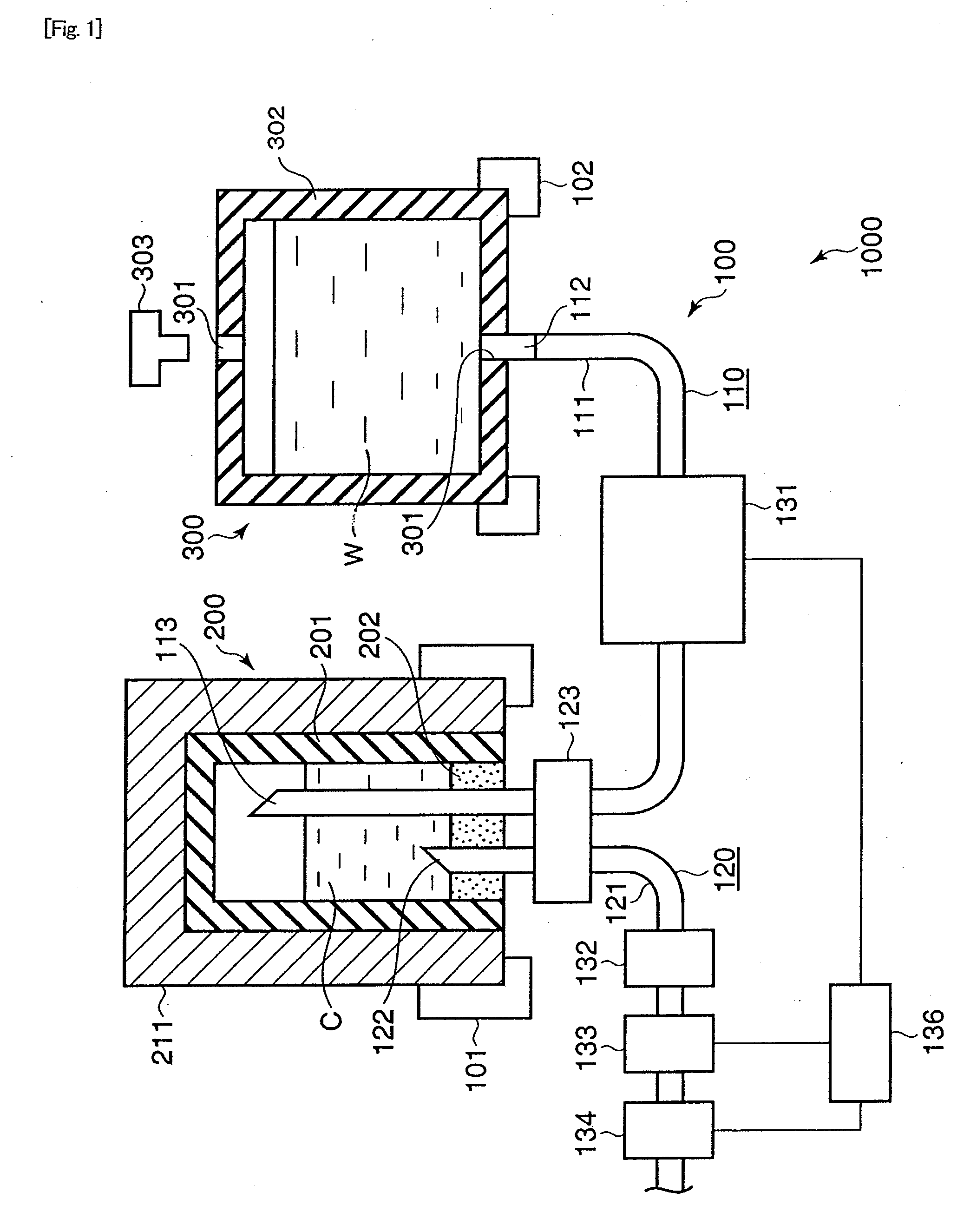
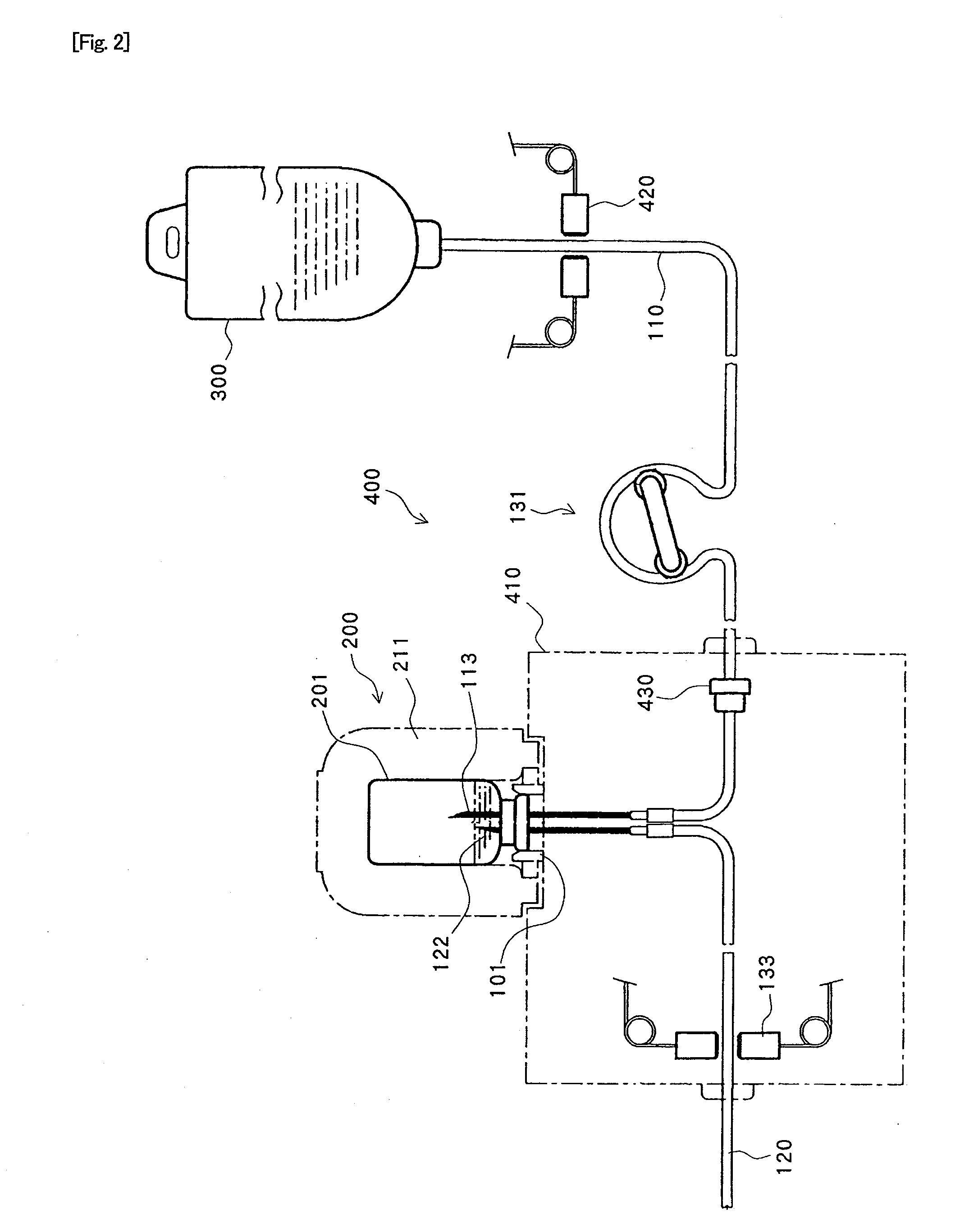
[0021]In the chemical liquid injection system of the present invention, the liquid pressure-feeding mechanism feeds the liquid in the liquid container from the liquid supply tube to the chemical liquid container with pressure to inject the chemical liquid in the chemical liquid container into the patient from the chemical liquid injection tube. For example, when a contrast medium is used as the chemical liquid and physiological saline is used as the liquid, it is possible to easily and reliably inject the contrast medium and then the physiological saline into the patient, and the chemical liquid can be injected directly into the patient from the chemical liquid container without using an intervening liquid syringe of the refill type or the like. Thus, radiation exposure of the operator can be prevented even when the contrast medium for the RI test is used as the chemical liquid.

Problems solved by technology

The operation is cumbersome and the structure of the chemical liquid injector is complicated.
The operation is complicated and the chemical liquid is likely to be contaminated during the transfer.
The operator who connects the extension tube to the liquid syringe is inevitably exposed to radiation.

Method used


Image

  • Chemical Liquid Injection System
  • Chemical Liquid Injection System
  • Chemical Liquid Injection System

Examples


embodiment

Configuration of Embodiment

[0050]An embodiment of the present invention will hereinafter be described with reference to drawings. Chemical liquid injection system 1000 of the present invention comprises chemical liquid injector 100 and replaceable chemical liquid container 200 which contains contrast medium C as a chemical liquid for PET.

[0051]More specifically, chemical liquid container 200 comprises cylindrical glass container body 201 having an opening formed at one end. The opening of container body 201 is sealed by elastic member 202 made of silicone rubber or the like. Since contrast medium C for PET is a radioactive material, container cover 211 made of tungsten for blocking the radiation is put outside container body 201.

[0052]Chemical liquid injector 100 has liquid container 300 which is replaceably provided for chemical liquid injector 100 separately from chemical liquid container 200. Liquid container 300 contains physiological saline W which is a liquid. Liquid container...


PUM


Abstract

A chemical liquid injection system with which a chemical liquid in a chemical liquid container can be directly injected into a patient without using an intervening liquid syringe or the like.A trailing end of chemical liquid injection tube 120 that its leading end is connected to the patient is placed at a lower position within chemical liquid container 200. A leading end of liquid supply tube 110 is placed at a upper position within chemical liquid container 200 and a trailing end of liquid supply tube 110 is connected to liquid container 300. Since liquid pressure-feeding mechanism 131 feeds the liquid in liquid container 300 into chemical liquid container 200 from liquid supply tube 110 with pressure, the chemical liquid is directly injected into the patient from chemical liquid container 200 through chemical liquid tube 120.

Description

TECHNICAL FIELD[0001]The present invention relates to a chemical liquid injection system which injects a chemical liquid put in a chemical liquid container into a patient with a chemical liquid injector.BACKGROUND ART[0002]Presently available diagnostic imaging apparatuses for capturing diagnostic images of patients include CT (Computed Tomography) scanners, MRI (Magnetic Resonance Imaging) apparatuses, PET (Positron Emission Tomography) apparatuses, SPECT (Single Photon Emission Computed Tomography) apparatuses, ultrasonic diagnostic apparatuses, angiography apparatuses, MRA (MR angiography) apparatuses and the like.[0003]When the abovementioned diagnostic imaging apparatuses are used, a chemical liquid such as a contrast medium may be injected into a patient. Chemical liquid injectors for automatically performing the injection have been put into practical use. A chemical liquid injector of the type described above includes an injection head on which a liquid syringe is removably m...

Claims


Application Information

Patent Timeline
IPC IPC(8): A61B6/00A61M5/00A61M5/14A61M5/142A61M5/145A61M5/168
CPCA61M5/007A61M5/14232A61M5/1452
Inventor NEMOTO, TORUIKOMA, TOMOYUKIFUKUDA, TAKASHI
Owner NEMOTO KYORINDO KK
Learn More