
Personal debris shield and system

a technology of personal debris and shield, which is applied in chemical protection, nuclear engineering, nuclear elements, etc., can solve the problems of time-consuming process, inapplicability, and inability to protect only a limited part of the body, and achieve the effect of quick donned and removed, facilitating survival and rescu

Inactive Publication Date: 2008-12-11
MONTGOMERY MICHAEL
View PDF64 Cites 5 Cited by
  • Summary
  • Abstract
  • Description
  • Claims
  • Application Information

AI Technical Summary

Benefits of technology

[0006]Briefly described, in a preferred embodiment, the device and system of the present disclosure overcome the above-mentioned disadvantages and meet the recognized need for such a device and system, and associated methods, by providing a personal debris shield that conforms to a user's body, preferably a user's back, neck, and head, to protect same from injury from falling, wind-driven, or other projectile debris, such as may encountered in a tornado, hurricane, earthquake, or the like.
[0007]The device preferably includes a force absorbing material, a stiff material, a puncture and / or laceration resistant material, combinations thereof, or the like, and is preferably adapted to be held in place and / or worn as a garment, whereby the device may quickly and easily be donned and removed for use. Thus, the device may preferably be held in place covering a back, neck, and / or head of the user, whereby the device may be removed in a situation in which it may be a hindrance, such as during running, crawling, swimming, or the like, and whereby the device may be secured to the user, such as via straps, clips, belts, or the like, such as for use as a flotation device or to prevent loss thereof.
[0008]According to its major aspects and broadly stated, the present invention, in its preferred form, is a personal debris shield comprising a body conforming to the back of a user and including at least one extension traversing the user's shoulders, whereby the user may preferably retain the shield covering the user's back via holding the extension, or by holding a strap or handle operable with the extension. The body preferably includes a stiff member, such as a sheet of acrylonitrile butadiene styrene, polycarbonate, polymethylmethacrylate, carbon fiber, aluminum, titanium, fiberglass, or the like. Such stiff member preferably defines a shape that is generally conformal to a back of user, and may be formed by stamping, molding, casting, machining, extrusion, combinations thereof, or the like. The stiff member preferably functions to prevent debris from piercing therethrough; thereby, reducing a risk of puncture and / or laceration wounds to a user. The stiff member preferably further functions to distribute a force of an impact over a larger portion of the user's body; thereby, reducing a pressure of the impact, and, thus, reducing a risk of blunt trauma, crushing injuries, or the like. In order to improve user comfort and to facilitate conformance of the device to a user's body, the stiff member may include corrugations, creases, folds, hinged or separate sections, or the like, to allow sufficient flexibility of the device.

Problems solved by technology

Helmets and other such garments function well for the purpose of preventing injuries, such as blunt trauma, lacerations, and punctures, but disadvantageously protect only a limited part of the body and restrict motion thereof.
This process is time-consuming, and not practical in emergency situations.
In any event, the mobility of the user may be severely limited by such garments while worn, thus discouraging use and potentially placing the user in harm's way.
While these devices have succeeded in increasing a protected area of the user's body while eliminating the need for multiple garments, they have done so at the further cost of mobility, and at the cost of ease of use.
Thus, while the user's neck may at least sometimes be protected, the user may be in a worse position overall due to the user's inability or reduced ability to detect and avoid dangers, caused by the limitation in the user's motion associated with the projection.
Thus, it is readily apparent that there exists an unmet need for a personal debris shield to protect against blunt trauma, lacerations, punctures, or the like, that may be donned quickly and easily in an emergency situation, and that reduces an adverse impact on the user's mobility and ability to quickly and easily remove and / or jettison the device.

Method used


Image

  • Personal debris shield and system
  • Personal debris shield and system
  • Personal debris shield and system

Examples


Embodiment Construction

[0025]In describing preferred embodiments of the present invention illustrated in the Figures, specific terminology is employed for the sake of clarity. The claimed invention, however, is not intended to be limited to the specific terminology so selected, and it is to be understood that each specific element includes all technical equivalents that operate in a similar manner to accomplish a similar purpose.

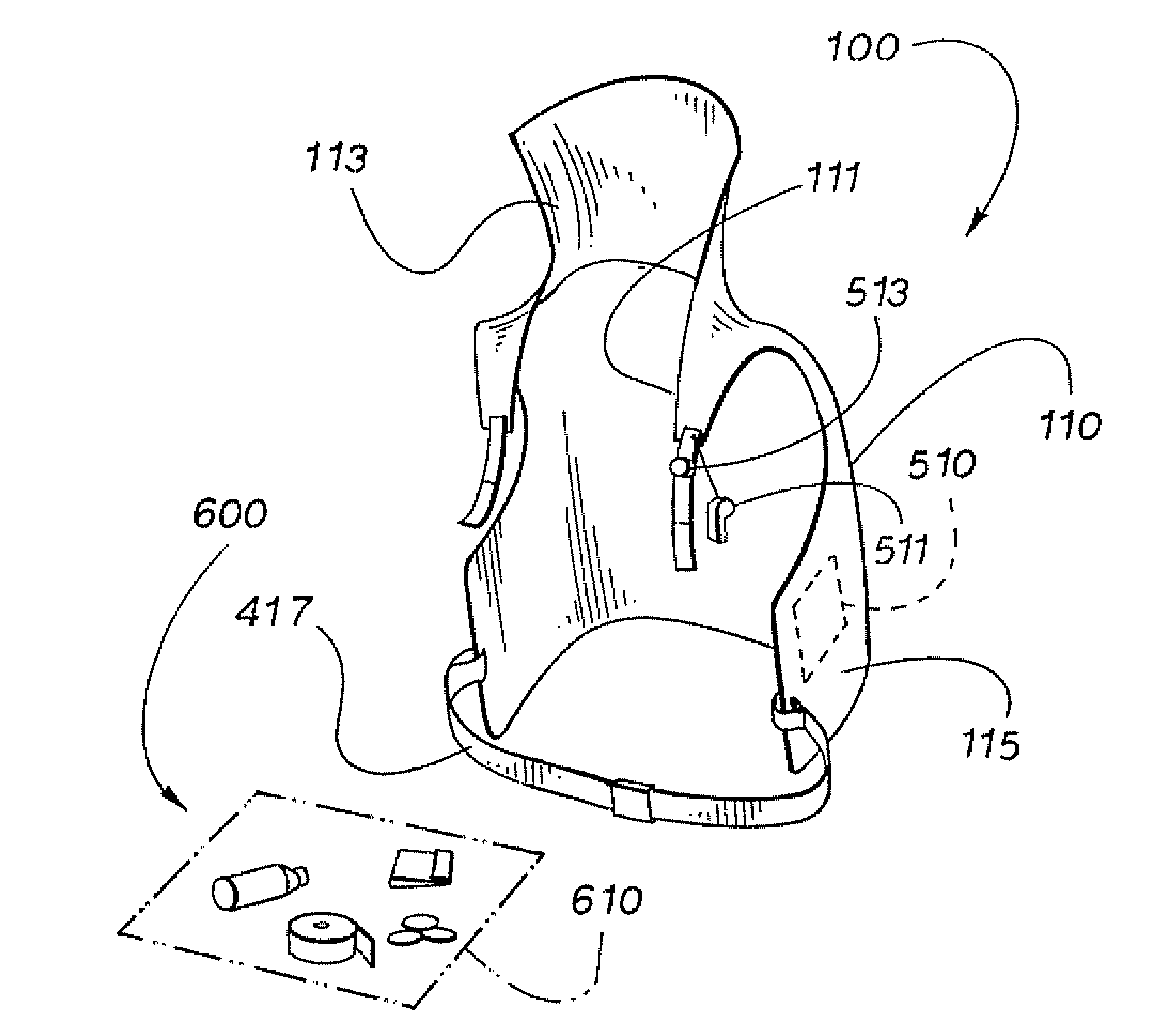
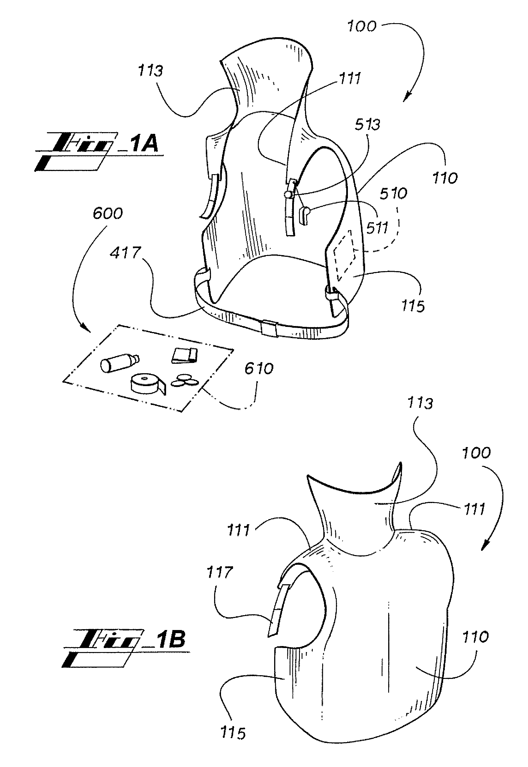
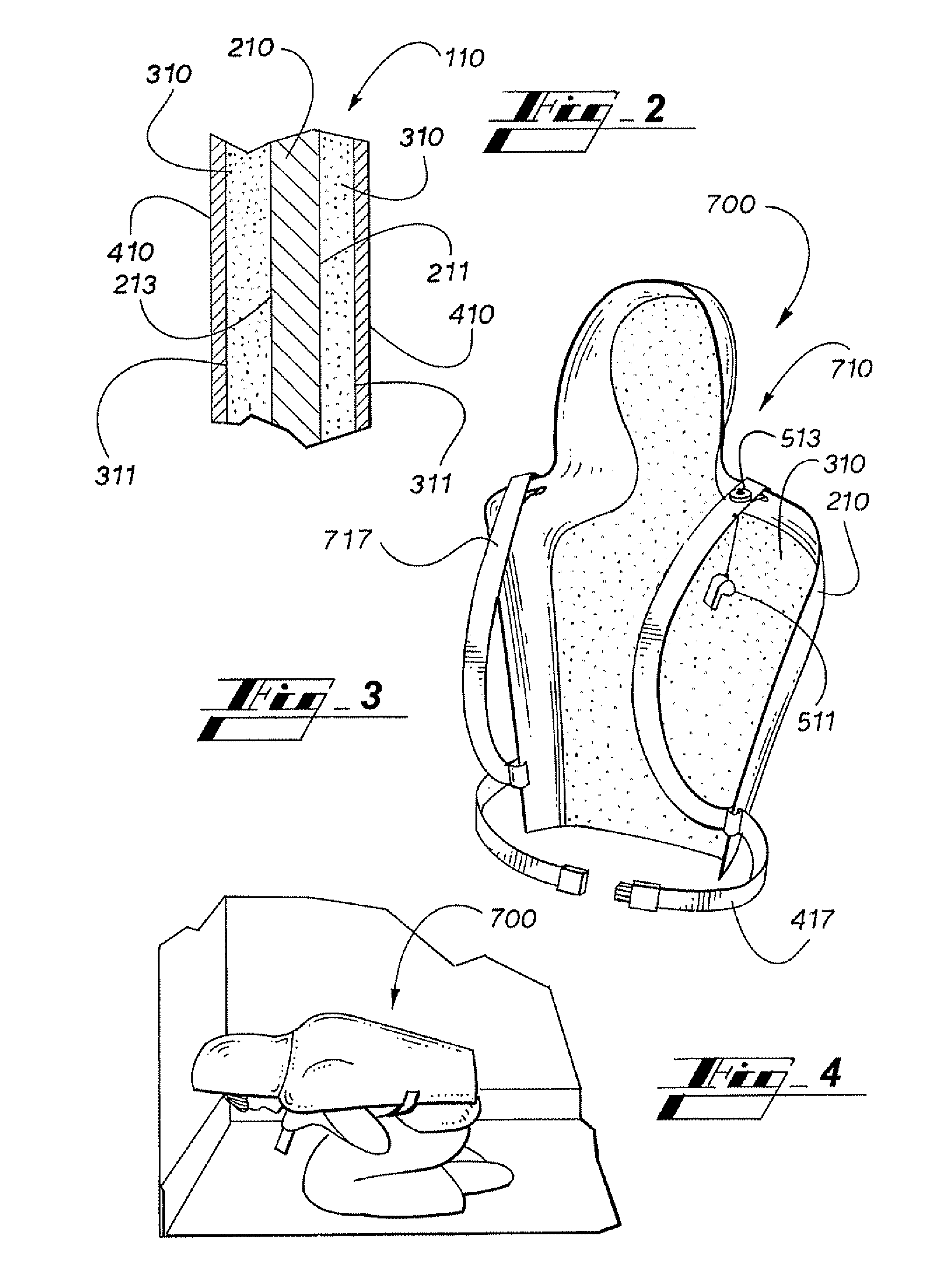
[0026]Now referring to FIGS. 1A-3, personal debris shield 100 is usable to protect a wearer against injury, such as that caused by falling, wind-driven, or other projectile debris. Personal debris shield 100 preferably comprises body 110 including shoulder extensions 111, neck projection 113, and abdomen extensions 115. Body 110 preferably includes a shape that is generally conformal to the back of a user, and may preferably also be generally conformal to the neck, head, shoulders, and / or ribs of a user. Body 110 preferably has sufficient structure to generally maintain such confo...


PUM


Abstract

A personal debris shield for use as a personal protection device to protect against falling or wind-driven debris, such as during a tornado, hurricane, earthquake, or the like, includes a body-conforming impact absorption shield that may be quickly positioned over a user's body and that may be removed and / or jettisoned if needed.

Description

RELATED APPLICATION[0001]The present non-provisional United States patent application is related to, and hereby claims priority to and the full benefit of, United States provisional application entitled “Personal Debris Shield and System” filed on Jun. 6, 2007 on behalf of Michael Montgomery, and having assigned Ser. No. 60 / 933,396.TECHNICAL FIELD[0002]The present disclosure relates generally to personal protection devices, and more specifically, to a personal debris shield and system.BACKGROUND OF THE INVENTION[0003]Over time, a wide variety of personal protection devices have been developed in order to prevent all manner of injuries. Many of these may be described as garments, intended to be worn by a user. Of such devices, helmets are demonstrative examples; they are designed to prevent injury to one of the most important and vulnerable parts of the body, the head. Helmets are designed to generally encase at least a portion of the head of the user, and attach thereto, such as wit...

Claims


Application Information

Patent Timeline
Patent Type & Authority Applications(United States)
IPC IPC(8): A41D13/00
CPCA41D13/015A41D13/05A41D2300/33
Inventor MONTGOMERY, MICHAEL
Owner MONTGOMERY MICHAEL
Learn More