Heat Exchanger Vessel With Means For Recirculating Cleaning Particles

a technology of heat exchanger and cleaning particles, which is applied in the direction of cleaning heat exchange devices, cleaning processes and apparatuses, lighting and heating apparatus, etc., can solve the problems of high and uneven wear of cooling tubes, uneven cleaning, etc., and achieve the effect of preventing backflow of particles, minimizing overall pressure drop and pumping duty

Inactive Publication Date: 2008-12-11
TWISTER BV
View PDF17 Cites 14 Cited by
  • Summary
  • Abstract
  • Description
  • Claims
  • Application Information

AI Technical Summary

Benefits of technology

[0014]Optionally, at least one distribution plate is arranged in the space between the outer surfaces of the heat exchanger tubes and the inner surface of the tubular mid section of the heat exchanger vessel to create an equally distributed flow of the cooling water and fluidized bed of cleaning particles throughout the height of the tubular mid section. The distribution plate may be a perforated plate and / or includes caps, nozzles or devices to preventing backflow of particles. The abrasive particles in combination with the distribution plates continuously remove the film-layer and mix the fluid flow, no baffles are required, minimizing the overall pressure drop and pumping duty.

Problems solved by technology

A disadvantage of the known method is that the cooling tubes are subject to high and uneven wear and are cleaned in an uneven manner.
Furthermore, the wall of the heat exchange is exposed to the high pressure and temperature of the exhaust gas, so that the heat exchanger vessel is a thick walled and heavy piece of equipment.

Method used


Image

  • Heat Exchanger Vessel With Means For Recirculating Cleaning Particles
  • Heat Exchanger Vessel With Means For Recirculating Cleaning Particles

Examples


Embodiment Construction

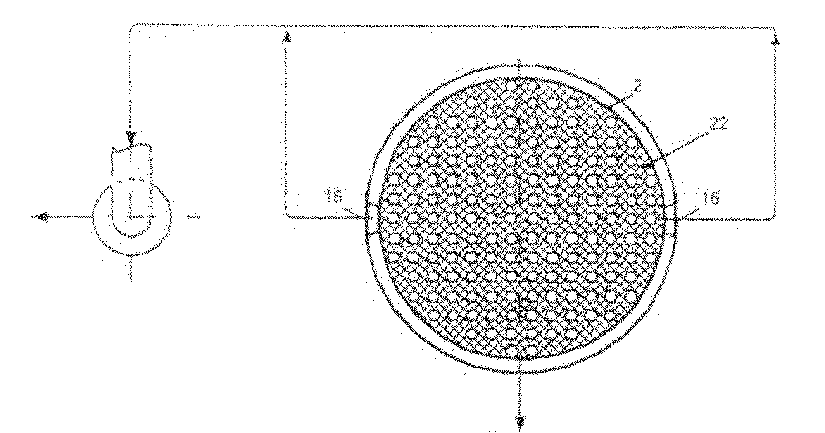
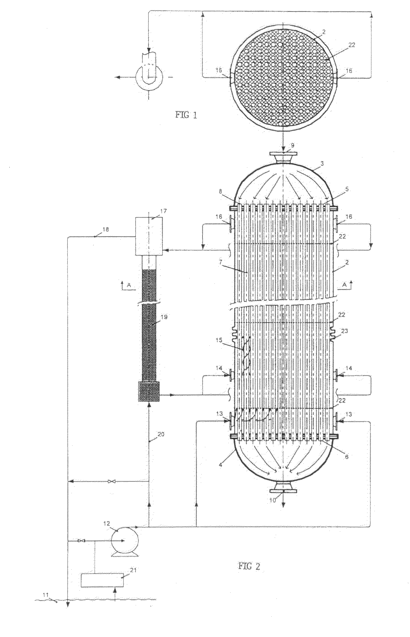
[0023]FIG. 1 shows a heat exchanger vessel 1 which has a tubular mid section 2 and dome-shaped top and bottom sections 3 and 4, known as headers, which are separated from each other by disc-shaped partitioning walls 5 and 6.

[0024]The tubular mid section 2 comprises a bundle of heat exchanger tubes 7 which extend through openings 8 in the disc-shaped partitioning walls 5 and 6 such that the interior of the heat exchanger tubes 7 is connected in fluid communication for the first fluid with the interior of the dome-shaped top and bottom sections 3 and 4.

[0025]An inlet 9 for a first fluid, which may be a high pressure and high temperature natural gas or other low or high pressure fluid, is arranged at the top of the dome-shaped top section 3. An outlet 10 for the first fluid is arranged at the bottom of the dome-shaped bottom section 4 of the vessel 1. In use the first fluid flows via the inlet 9 into the interior of the top section 3 of the vessel 1 and flows via the interior of the bu...


PUM


Abstract

A heat exchanger vessel (1) comprises a tubular outer shell (2) in which a bundle of heat exchanging tubes (7) is arranged, which bundle of heat exchanger tubes is coupled to an inlet (9) and outlet (10) for a first fluid, such as high-pressure natural gas, and the tubular outer shell (2) comprises at least one inlet (13,14) and at least one outlet (16) for a second fluid, such as seawater, wherein at least one inlet (14) for the second fluid is provided with particle injection means for injecting cleaning particles into the space between the outer surfaces of the heat exchanger tubes (7) and the inner surface of the tubular shell (2) of the heat exchanger vessel (1) and at least one outlet (16) for the second fluid is connected to means for removing particles from the second fluid and for recirculating particles to at least one inlet (14) of the second fluid. The mildly abrasive cleaning particles will remove any fouling or scaling from the space between the heat exchanger tubes (7) and the outer shell (2) so that the second fluid, such as seawater, can be heated to a relatively high temperature and circulated at low velocity, resulting in a relatively compact and lightweight heat exchanger vessel with low maintenance requirements; enabling (direct) subsea seawater cooling.

Description

BACKGROUND OF THE INVENTION[0001]The invention relates to a heat exchanger (HEX) vessel with means for recirculating cleaning particles.[0002]It is known from U.S. Pat. Nos. 5,706,884, 5,676,201, 6,073,682 and 6,109,342 to provide a heat exchanger vessel in which a bundle of heat exchanger tubes is provided with means for circulating cleaning particles through the tubes to remove any fouling from the inner walls of the tubes.[0003]It is known from U.S. Pat. Nos. 6,070,652 and 6,223,809 to recirculate balls through a bundle of heat exchanger tubes to remove any fouling from the inner walls of the tubes.[0004]The known systems are solely designed for cleaning the inner walls of heat exchanger tubes in a heat exchanger vessel.[0005]The heat exchanger according to the preamble of claims 1 and 11 is known from German patent DE 1083058. In the known heat exchanger exhaust gases are cooled in a heat exchanger, which comprises tubes through which cooling water is circulated and the cleaning...

Claims


Application Information

Patent Timeline
Patent Type & Authority Applications(United States)
IPC IPC(8): F28G1/12
CPCF28D7/16F28G1/12
Inventor KRAGT, BEREND-JANTJEENK WILLINK, CORNELIS ANTONIE
Owner TWISTER BV
Why Eureka
Try Eureka