Detachable hydrofoil trim tabs for use with seaplane floats for assisting with lower speed on-plane condition and stability during step turning/chine walk manuevers

a technology of hydrofoil and trim tabs, which is applied in the direction of floats, special-purpose vessels, vessel construction, etc., can solve the problems of wing breaking off, minor damage to the fin and float, and the integrity of the float being breached, so as to maximize the ease of removal and provide a degree of flexibility

Active Publication Date: 2008-12-11
CHARLY CENT
View PDF15 Cites 18 Cited by
  • Summary
  • Abstract
  • Description
  • Claims
  • Application Information

AI Technical Summary

Benefits of technology

[0009]In a preferred application, either or both the first and second portions of the tab are constructed of a flexible and durable material, such as including an aluminum or polymer, the advantage of which is to provide a degree of flexibility, thus permitting the tab to flex or bend in response to chine / walking forces of intermediate severity, and to revert back to its original shape In this fashion, inadvertent breakage of a trim tab at the frangible location, such as a result of excessive hydraulic forces resulting from walking or chine of the plane upon the surface of the water, or the possible incidence of an object in the water hitting the tab associated with the moving float, will cause only the second portion to detach, thereby preventing damage to the associated float.
[0010]Additional applications include both the first and second portions capable of being easily removed from each of the seaplane floats, and such as to allow conventional ground handling equipment / trailers to transport the trailer without damage to the fin or float. It is also envisioned that the fin design can be either retrofit mounted to an existing float or, in additional preferred applications, can be manufactured into the originally designed float, and such as to maximize the ease of removability, such as further through the use of channel and slot engagement between the first portion and the surface of the float, and as an alternative to the use of mechanical fasteners, seam welding or the like.

Problems solved by technology

In practice, and as a result of forces of the water acting upon the float chine during both takeoff and landing (this defined to be the angular intersection of the sides and bottom of the float), there exists a tendency for the wing to break off, and which in more extreme situations will involve the integrity of the float being breached and, as a result, sunk.
Minor damage to the fin and float as a result of mishaps involving improperly designed ground handling equipment can occur, and which the pilot might not see during such as pre-flight procedures.
Given further that the fin is submerged underneath the float at the time of launch, the occurrence of such damage is often missed.
Another disadvantage associated with fixed mounted wings or fins, such as again illustrated by Center, concerns the ability of ground handling personnel to launch and / or retrieve a seaplane craft exhibiting a fixed mounted fin associated with the float, and such as is typically caused by the requirement of mounting the fins through the drilling of specialty rivets.
Removal of the rivets cannot typically be accomplished without inflicting damage to the wing and / or the integrity of the float.
Furthermore, conventional ground handling equipment available at most maintenance and storage facilities does not provide clearance for the fixed in place fin interference (this further measured in one application as a distance between the internal distance between the left and right mounted fins).
Given the relatively small number of aircraft currently equipped with fixed wings such as shown in Center, the likelihood of such aircraft handling facilities investing in such equipment is relatively low.

Method used


Image

  • Detachable hydrofoil trim tabs for use with seaplane floats for assisting with lower speed on-plane condition and stability during step turning/chine walk manuevers
  • Detachable hydrofoil trim tabs for use with seaplane floats for assisting with lower speed on-plane condition and stability during step turning/chine walk manuevers
  • Detachable hydrofoil trim tabs for use with seaplane floats for assisting with lower speed on-plane condition and stability during step turning/chine walk manuevers

Examples


Embodiment Construction

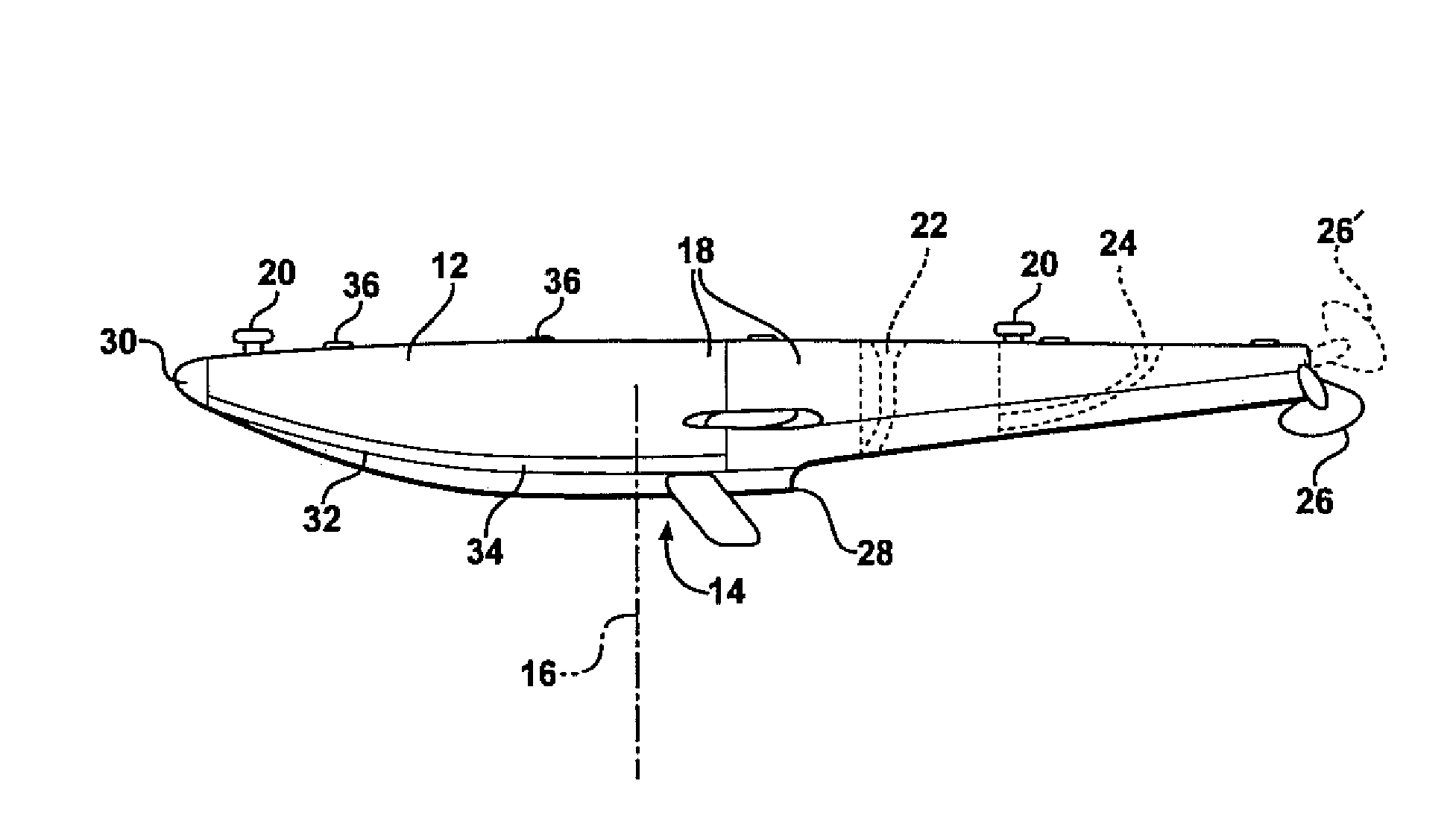
[0021]The present invention discloses a hydrofoil (i.e. trim tab) design for assisting in establishing an on-plane relationship of a buoyant and propelling craft. More particularly, the present invention discloses a trim tab design capable of being incorporated in inwardly acing and opposing fashion relative to a pair of seaplane floats.

[0022]As will be further described in subsequent detail, the trim tabs are typically constructed of a flexible and resilient material, such as an aluminum or polymeric resin, and in order to promote detachability in the instance of excessive chine / walking forces, or of an object striking the tab. In a preferred application, the tab is located just aft of a center of buoyancy associated with each float, one aspect of which is in order to maximize the rate at which an on-plan condition of the float is achieved during takeoff.

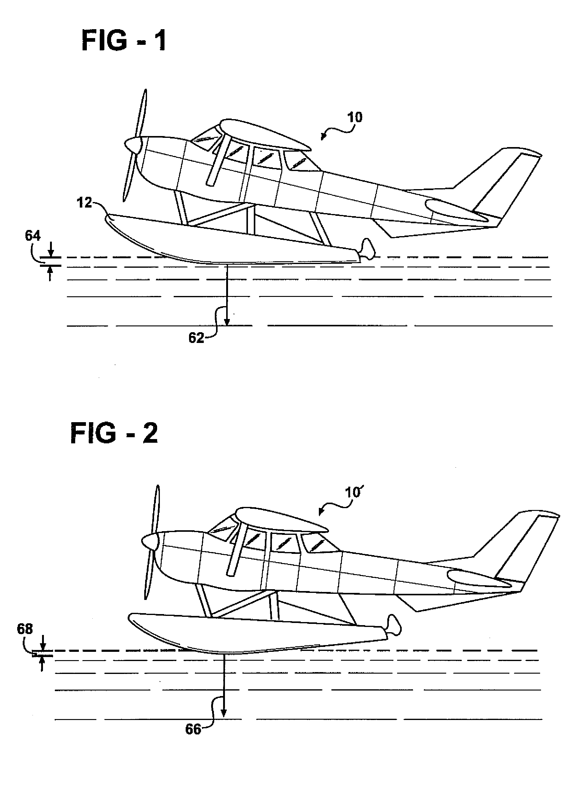
[0023]Referring now to FIG. 1, a first illustration is shown at 10 of a seaplane in a nose up (pre-planing) configuration associa...


PUM


Abstract

A hydrofoil trim tab for use with each of a pair of seaplane floats, each tab including a substantially planar shaped body secured to an inside facing location of each float such that a pair of tab bodies are arrayed in opposing and inwardly directed fashion relative to the floats. Each tab is further constructed as a two piece article, a first portion being either mechanically secured or welded to the surface of the float, with a second portion being releasably / breakaway attached to the first portion, such as by frangible fasteners engaging a slidably connection location between the portions. In this fashion, inadvertent breakage of a trim tab at the frangible location will prevent damage to the float.

Description

CROSS-REFERENCE TO RELATED APPLICATIONS[0001]This application is a Non-Prov of Prov (35 LUSC 119(e)) application 60 / 866,925 filed on Nov. 22, 2006 and entitled RESIN CONSTRUCTABLE AND DETACHABLE HYDROFOIL TRIM TABS FOR USE WITH SEAPLANE FLOATS FOR ASSISTING WITH LOWER SPEED ON-PLANE CONDITION AND STABILITY DURING TURNING / CHINE WALK MANEUVERS.FIELD OF THE INVENTION[0002]The present invention is directed to hydrofoil (i.e., trim tab) design for assisting in establishing an on-plane relationship of a buoyant and propelling craft. More particularly, the present invention discloses a trim tab design capable of being incorporated in inwardly facing and opposing fashion relative to a pair of seaplane floats. The trim tabs are typically constructed of either a metallic or a resinous material, such as in a two-piece fashion, to promote detachability in the instance of an object striking the tab, and are typically located just aft of a center of buoyancy associated with each float.BACKGROUND ...

Claims


Application Information

Patent Timeline
Patent Type & Authority Applications(United States)
IPC IPC(8): B63B1/00B64C25/54
CPCB63B39/061B64C25/54
Inventor FILIPEK, GERALD
Owner CHARLY CENT
Why Eureka
Try Eureka