Habitation and sleeping module for accommodating at least one member of a flight crew

a technology for flight crew and habitation, which is applied in the direction of aircraft crew accommodation, seating arrangements, transportation and packaging, etc., can solve the problem of reducing the risk of passengers bumping their heads against the ceiling, and achieves the effect of high level of privacy

Active Publication Date: 2008-12-11
AIRBUS OPERATIONS GMBH
View PDF15 Cites 14 Cited by
  • Summary
  • Abstract
  • Description
  • Claims
  • Application Information

AI Technical Summary

Benefits of technology

[0008]A habitation and sleeping module for an aircraft for accommodating at least one member of the flight crew is stated, wherein a first sleeping area and an ascent region for ascending or climbing up from a lower level, e.g. a lower level of the aircraft cabin, to the module are provided. Likewise, the ascent region comprises an ascent device that is arranged laterally on the module. In this arrangement the first sleeping area can comprise one or several lying-down facilities. The term “lying-down facility” refers to any device that may make it possible for a person to assume a lying-down rest- and sleep position. The lying-down facility may be a simple foam material support; however, an anatomically matching form of the elements as well as special constructions may also be possible in order to provide a comfortable extended period of rest in a lying-down position. In this arrangement in particular a design as a bed, couchette, plank bed, folding bed, hingeable bed and any further embodiment of a lying-down facility may be possible. In this arrangement in each exemplary embodiment of the present invention variants of a folding bed may, in particular, provide the option, in the folded-in state, of being used as a table or a sideboard. If only part of the bed is folded out, the remaining part of the bed may also be used as a storage or stowage compartment. Furthermore, in a variant of a folding bed there is the option, when the bed is folded in, of gaining base area and thus freedom of movement. This may result in an increase in module comfort.
[0049]In this context the term “TTL-certifiable seating facility” refers to its use as a taxi-takeoff and landing seat. Especially by its arrangement in the form of a specially designed seat it is possible to certify the first seating facility as a TTL seating facility. In this way a comparable seating facility for flight crew in the passenger region can be done without, which can result in further freedom of design and in possible savings in weight.

Problems solved by technology

Likewise the increased danger of passengers bumping their heads against the ceiling may be counteracted.

Method used


Image

  • Habitation and sleeping module for accommodating at least one member of a flight crew
  • Habitation and sleeping module for accommodating at least one member of a flight crew
  • Habitation and sleeping module for accommodating at least one member of a flight crew

Examples


Embodiment Construction

[0091]Below, exemplary embodiments of the present invention are described with reference to the figures.

[0092]In the following description of the figures, the same reference characters are used for identical or similar elements.

[0093]Below, the present invention is described by means of several preferred embodiments of the habitation and sleeping module according to an exemplary embodiment of the invention. However, the explanations provided also apply to an aircraft comprising a corresponding module, and to the use of a corresponding module in an aircraft.

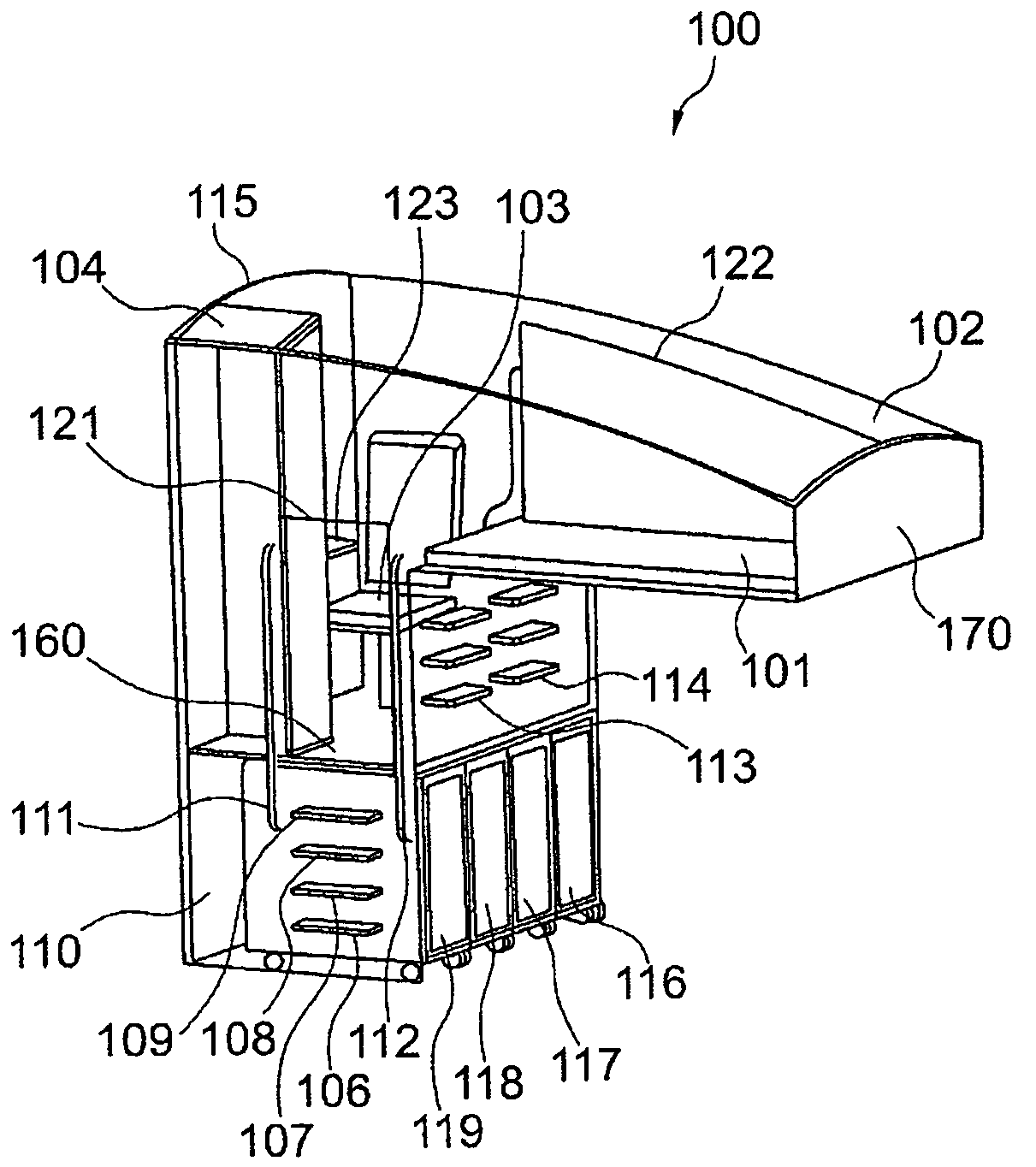
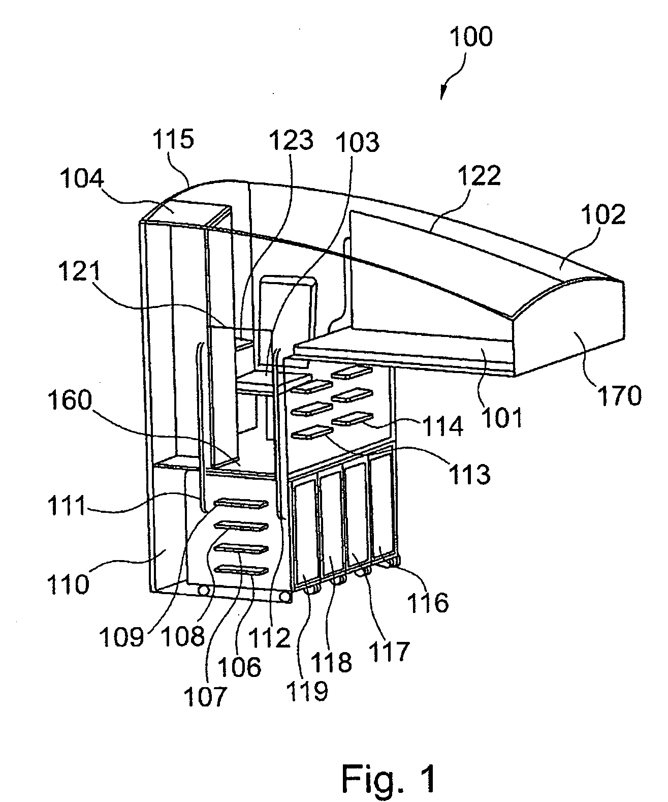
[0094]FIG. 1 shows a diagrammatic three-dimensional view of the habitation and sleeping module 100 according to an exemplary embodiment of the invention. By way of an ascent region 110 a crew member can climb up to the module and enter it. This ascent region comprises so-called ascent devices, in the example shown they are four individual steps 106 to 109 and two handrails 111 and 112. In this arrangement the term “handrail”112 re...


PUM


Abstract

A habitation and sleeping module, in an aircraft, for accommodating at least one member of a flight crew, with the module having a first sleeping area. Furthermore, an ascent region is provided for ascending from a lower level into the module, wherein the ascent region includes an ascent device that is laterally arranged on the module.

Description

CROSS-REFERENCE TO RELATED APPLICATIONS[0001]This application claims the benefit of the filing date of U.S. Provisional Patent Application No. 60 / 925,987 filed Apr. 24, 2007, the disclosure of which is hereby incorporated herein by reference.BACKGROUND OF THE INVENTION[0002]The present invention relates to flight crew rest compartments in aircraft. In particular, the present invention relates to a habitation and sleeping module for accommodating at least one member of a flight crew, to an aircraft comprising a corresponding module, and to the use of a corresponding module in an aircraft.[0003]Flight crew rest compartments (FCRCs) form part of the mandatory equipment of aircraft on long-duration flights. According to international standards, any flight of a duration of between 8 h and 14 h requires one lying-down facility, while flights exceeding 14 h require two lying-down facilities. This is also derived from the requirement wherein from a certain flight duration onwards a total of...

Claims


Application Information

Patent Timeline
Patent Type & Authority Applications(United States)
IPC IPC(8): B64D11/06
CPCB64D11/00B64D2011/0076Y02T50/46Y02T50/40
Inventor WARNER, HOLGERHELFRICH, FELIX
Owner AIRBUS OPERATIONS GMBH
Why Eureka
Try Eureka