
Bypass air release quench chamber device

A technology for bypassing air and quenching chamber, which is used in lighting and heating equipment, gas treatment, direct contact heat exchangers, etc. and other problems, to achieve the effect of rapid enrichment, flexible layout and reasonable structure

Inactive Publication Date: 2020-09-15
TIANJIN CEMENT IND DESIGN & RES INST
View PDF6 Cites 0 Cited by
  • Summary
  • Abstract
  • Description
  • Claims
  • Application Information

AI Technical Summary

Problems solved by technology

[0005] Aiming at the problems existing in the prior art, the present invention provides a bypass air quenching chamber device which solves the problems of poor mixing effect of cold and hot air in the quenching chamber of the existing cement kiln and high dust content in the exhausted air from the quenching chamber

Method used


Image

  • Bypass air release quench chamber device
  • Bypass air release quench chamber device
  • Bypass air release quench chamber device

Examples


Embodiment 2

[0039] The quenching chamber device described in this example is used in a cement production line. Due to waste disposal and chlorine element exceeding the standard, a bypass scheme needs to be set up. According to the material balance, the air discharge volume is calculated to be 5%. Rotary kiln flue gas needs to be taken out. Ambient air enters the quench chamber through the blower as the cooling medium. Because the sulfur content in the flue gas is also high, it is necessary to spray lime at the outlet of the quenching chamber, so the temperature at the outlet of the quenching chamber is controlled at 400-450°C. After heat balance calculation, the required quench chamber diameter is 1.6m, and the design wind speed of each quench chamber is as follows:

[0040] Wind speed of hot air in the settling chamber: 6m / s; wind speed of cold air inlet in the quenching chamber: 20-25m / s; wind speed at the annular inlet of the quenching chamber: 10-15m / s; wind speed of hot air entering...

Embodiment 3

[0046] see Figure 4 , the present embodiment is the purifying system comprising this quenching chamber device, and the outlet of the quenching chamber of the quenching chamber device is connected in series successively with a cyclone dust collector 5, a dust collector 6, a blower fan 7, an exhaust gas treatment system 8 and a chimney 9, and the cyclone The dust outlet of the dust remover 5 communicates with the quench chamber 2 . The cyclone dust collector 5, the dust collector 6, the fan 7, the waste gas treatment system 8 and the chimney 9 are conventional structures in the field, and the cyclone dust collector 5 collects dust from the gas discharged from the quench chamber 2 and enters the calciner of the cement kiln system. At this time, the amount of ash returned decreases, and the total amount of hot air taken out of the smoke chamber increases. Combined with the layout of the cement production line, the bypass flue gas passes through the fan 7 and is introduced into t...

Embodiment 4

[0048] see Figure 5 , on the basis of Embodiment 1, after the outlet of the quench chamber 2, the humidification tower 10, the dust collector 6, the fan 7, the exhaust gas treatment system 8 and the chimney 9 are connected in series. The humidifying tower 10, the dust collector 6, the fan 7, the waste gas treatment system 8 and the chimney 9 are conventional structures in the field. The humidifying tower 10 cools the flue gas discharged from the quench chamber, and the air volume of the dust collector will decrease at this time. .


PUM

PropertyMeasurementUnit
Lengthaaaaaaaaaa

Abstract

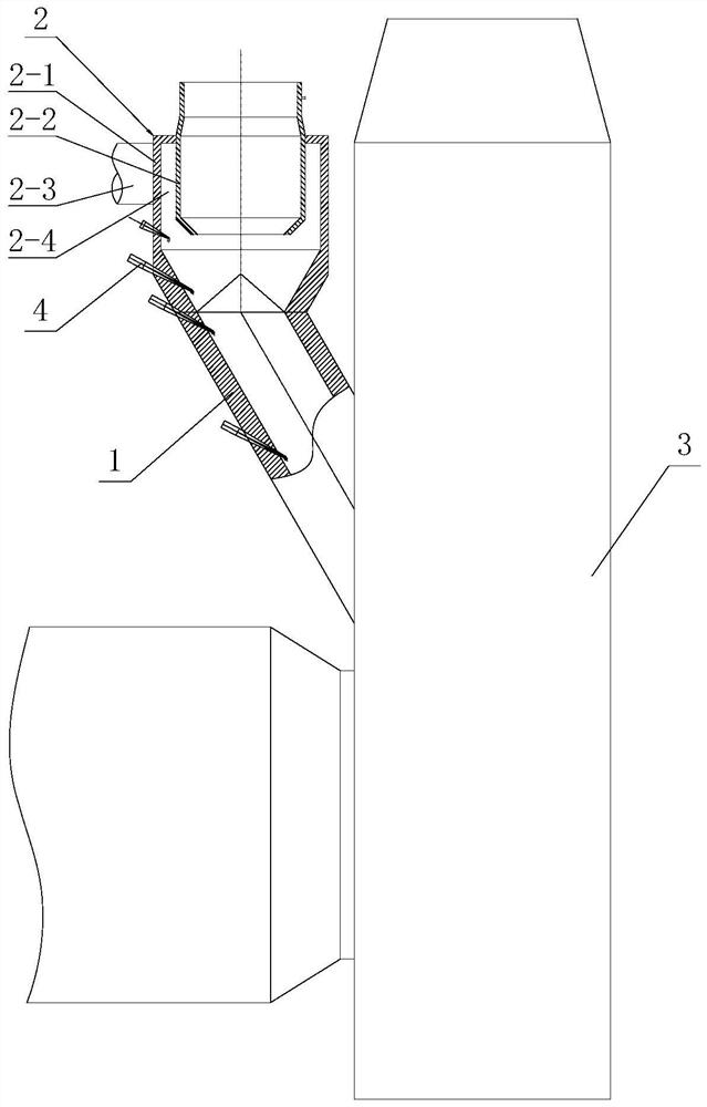
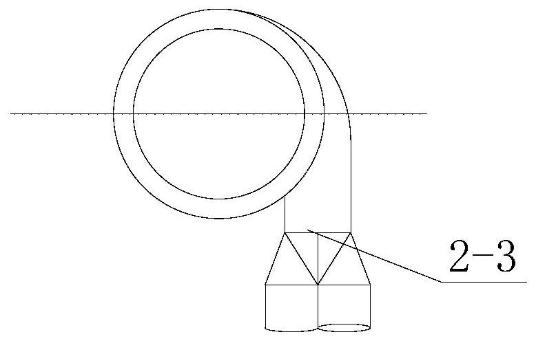
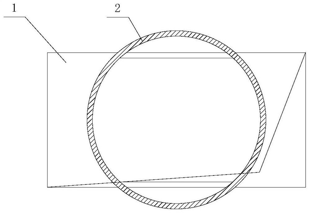
The invention discloses a bypass air release quench chamber device. The bypass air release quench chamber device is characterized by comprising a hot air settling chamber and a quench chamber connected with the hot air settling chamber; the hot air settling chamber is provided with a settling channel penetrating through the two ends; and the quench chamber comprises an outer cylinder, an inner cylinder and a volute, the inner cylinder is arranged on the inner side of the outer cylinder, an annular duct is formed between the inner cylinder and the outer cylinder, one end of the outer cylinder is a hot air inlet communicated with an outlet of the settling channel of the hot air settling chamber, the other end of the outer cylinder is connected with the outer wall of the inner cylinder, the end, away from the hot air inlet, of the inner cylinder is a quench chamber outlet, a cold air inlet capable of guiding air into the inner side of the outer cylinder in the tangential direction of theinner wall of the outer cylinder is formed in the outer side of the end, close to the quench chamber outlet, of the outer cylinder, and the volute is communicated with the cold air inlet. The quench chamber device is high in hot flue gas cooling speed, high in cold and hot air mixing efficiency, small in overall structure, convenient to arrange and easy to operate and maintain, coarse sedimentation discharge is reduced, and rapid enrichment of harmful ingredients is facilitated.

Description

technical field [0001] The invention belongs to the technical field of cement production equipment, and in particular relates to a bypass air release quench chamber device. Background technique [0002] Comprehensive utilization of resources and green development are inevitable trends in the development of the cement industry. More and more cement plants are trying to dispose of waste and reuse inferior raw materials in response to the national policy call for protecting natural resources. In Europe, cement plants burning a single fuel no longer exist. The average proportion of alternative fuels in the cement industry in EU countries has reached 30%, Germany has reached an average level of 50%, and the proportion of alternative fuels in individual cement plants has reached 75%. Cement plants in developed countries, especially those near cities and towns, are emphasizing their contribution to environmental protection. At present, in my country's cement industry, the substitu...

Claims


Application Information

Patent Timeline
IPC IPC(8): B01D53/75B01D45/02B01D53/83B01D45/16B01D53/50B01D53/56B01D53/68B01D53/76F28C3/02
CPCB01D45/02B01D45/16B01D53/508B01D53/56B01D53/68B01D53/75B01D53/76B01D2258/0233F28C3/02
Inventor 马娇媚胡芝娟赵亮高为民
Owner TIANJIN CEMENT IND DESIGN & RES INST
Learn More