Lamp With Light Absorbing Coating

a technology of light absorbing coating and lamp body, which is applied in the direction of coatings, incadescent envelopes/vessels, transportation and packaging, etc., can solve the problems of bulky, complicated assembly process, and loss of light emitted towards the roo

Inactive Publication Date: 2008-12-11
KONINKLIJKE PHILIPS ELECTRONICS NV
View PDF4 Cites 1 Cited by
  • Summary
  • Abstract
  • Description
  • Claims
  • Application Information

AI Technical Summary

Benefits of technology

[0006]It is an object of the invention to provide a tubular lamp which avoids loss of light and emits light with a colour different from the colour of light emitted by the light source.
[0008]In addition to the reflective coating which aims at avoiding loss of light, the lamp in accordance with the invention comprises, on a part of the lamp vessel, a light absorbing coating comprising pigments. This light absorbing coating absorbs certain wavelengths of the light emitted by the light source, so that the colour of said light is modified when passing through said light absorbing coating. By suitably choosing the pigments, the desired colour can be obtained.
[0010]Advantageously, the first part is distinct from the second part. This means that the light absorbing coating is not present where the reflective coating is present. This avoids employing more light absorbing coating than necessary. Moreover, if the first part is not distinct from the second part and if the reflective coating and the light absorbing coating are on the external surface of the lamp vessel, a part of the reflective coating is deposited on a part of the light absorbing coating, or vice versa. Now, the deposition of the reflective coating on the light absorbing coating might alter the light absorbing coating, and vice versa. Having the first part distinct from the second part alleviates this drawback.

Problems solved by technology

Without any reflector, the light emitted towards the roof is thus lost.
Moreover, the use of a reflective coating avoids use of an external reflector, which is bulky and requires a complicated assembly process.

Method used


Image

  • Lamp With Light Absorbing Coating
  • Lamp With Light Absorbing Coating
  • Lamp With Light Absorbing Coating

Examples


Embodiment Construction

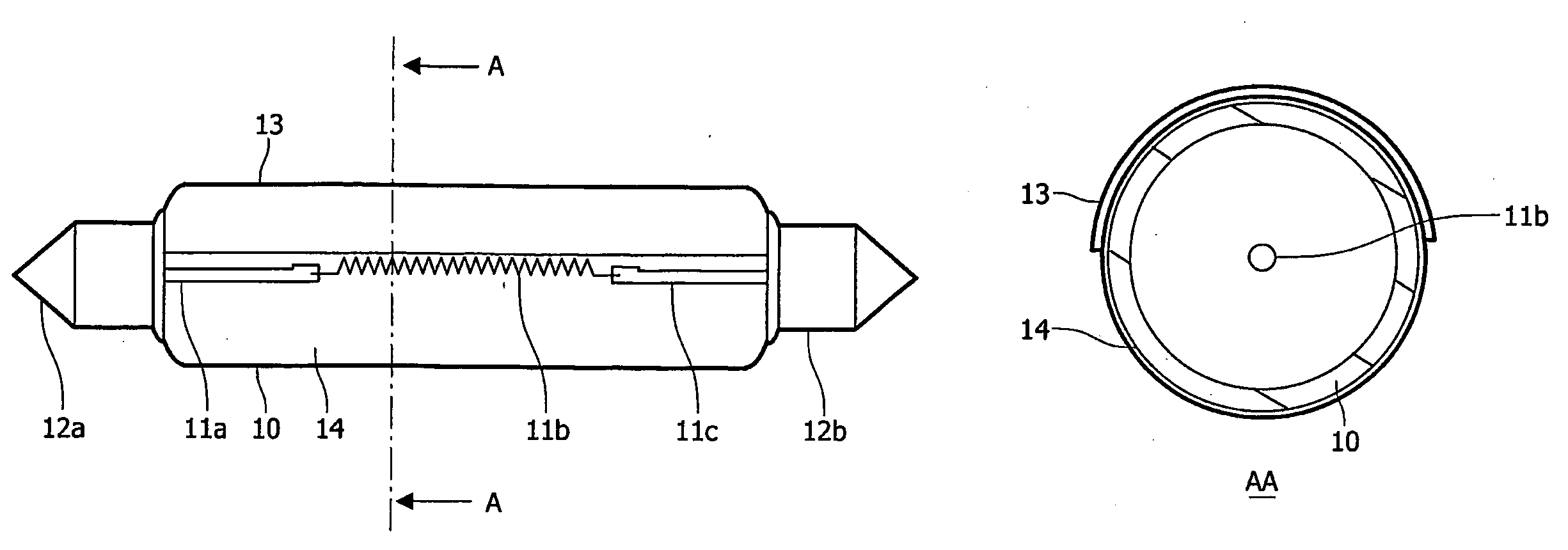
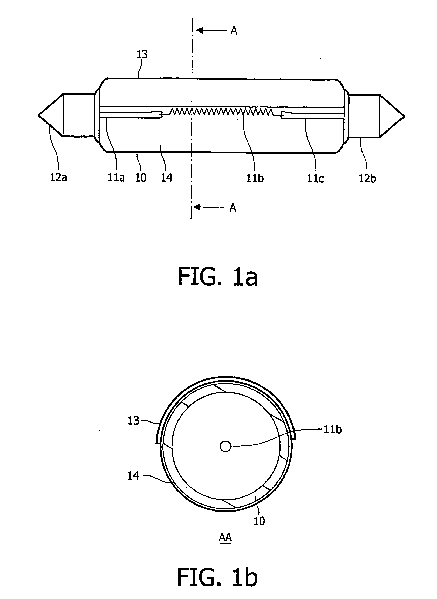
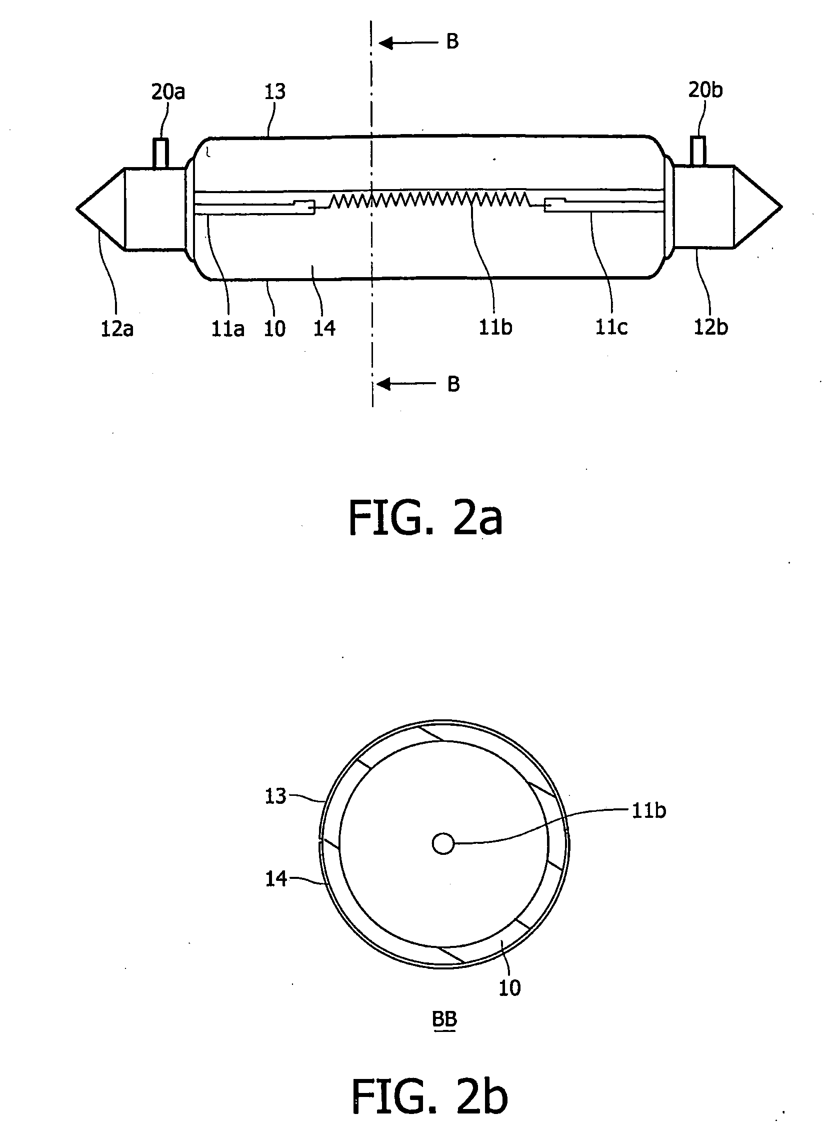
[0019]A lamp in accordance with the invention is depicted in FIGS. 1a and 1b. FIG. 1b is a cross section in the plane AA of FIG. 1a. Such a lamp is of the festoon type, although the invention applies to other types of lamp. The lamp comprises a lamp vessel 10, a light source comprising a first straight section of nickel plated dumet 11a, a coiled wire 11b and a second straight section of nickel plated dumet 11c, a first end cap 12a, a second end cap 12b, a reflective coating 13 and a light absorbing coating 14. In FIG. 1a, the light absorbing coating 14 is represented transparent, but it might be translucent such that the light source is not visible when the lamp is viewed from the exterior.

[0020]It should be noted that the thickness of the reflective coating 13 and the light absorbing coating 14 is emphasized in FIG. 1b, for reasons of convenience. For example, the lamp vessel 10 has a thickness of 1 millimetre and the reflective coating 13 and the light absorbing coating 14 have a...


PUM

PropertyMeasurementUnit
thicknessaaaaaaaaaa
temperatureaaaaaaaaaa
thicknessaaaaaaaaaa

Abstract

The invention relates to a tubular lamp comprising a lamp vessel (10) which accommodates a light source (11a, 11b, 11c). A first part of the lamp vessel is provided with a coating (13) reflective of radiation emitted by said light source. A second part of the lamp vessel is provided with a light-absorbing coating (14). The light absorbing coating comprises pigments incorporated in a sol gel matrix.

Description

FIELD OF THE INVENTION[0001]The present invention relates to a tubular lamp comprising a lamp vessel which accommodates a light source, wherein a first part of the lamp vessel is provided with a coating reflective of radiation emitted by said light source.[0002]The present invention also relates to a tubular lamp vessel having a first part provided with a reflective coating, as well as a luminaire comprising a tubular lamp.[0003]The present invention is particularly relevant for automotive lamps, such as lamps used for interior lighting of a car.BACKGROUND OF THE INVENTION[0004]A tubular lamp comprising a lamp vessel which accommodates a light source, wherein a first part of the lamp vessel is provided with a coating reflective of radiation emitted by said light source is known from U.S. Pat. No. 4,710,677. In such a lamp, a coating of a suitable reflective material is applied to a part of the surface of the lamp vessel, in order to maximise the amount of radiation available for use...

Claims


Application Information

Patent Timeline
Patent Type & Authority Applications(United States)
IPC IPC(8): B60Q1/00H01J61/02H01J61/35H01J61/40C03C17/00C03C17/36H01K1/20H01K1/32
CPCC03C17/36C03C17/3642C03C17/3657C03C17/3684C03C2217/45C03C2217/475C03C2217/485C03C2218/113H01J61/025H01J61/30H01J61/35H01J61/40H01K1/20H01K1/32
Inventor LE PARC, MEDERICBROERSMA, REMY CYRILLERAME, JEAN-FRANCOISSTRAETMANS, JEAN-SEBASTIEN
Owner KONINKLIJKE PHILIPS ELECTRONICS NV
Why Eureka
Try Eureka