System and method for thermal analysis using variable thermal resistance

a variable thermal resistance and thermal analysis technology, applied in the direction of heat measurement, material heat development, instruments, etc., can solve the problems of limited cooling rate, inconvenient operation, and limited cooling rate of apparatus described in the '733 paten

Active Publication Date: 2008-12-11
WATERS TECH CORP
View PDF27 Cites 18 Cited by
  • Summary
  • Abstract
  • Description
  • Claims
  • Application Information

AI Technical Summary

Benefits of technology

[0010]In one configuration of the present invention, a thermal measurement system comprises a measurement assembly having a differential thermal analysis sensor assembly for receiving a sample that is installed in a cavity within an elongated cylinder, an infrared lamp assembly disposed circumferentially around the elongated cylinder and having a length substantially similar to that of the cylinder. The infrared lamp assembly preferably comprises a plurality of tubular lamps each having a longitudinal axis arranged parallel to the axis of the elongated cylinder, and an infrared reflector comprising a plurality of partial quadric cylindrical surfaces that each describe a cylindrical shape that has a focus coincident with the axis of each tubular lamp. The thermal measurement system further comprises a thermal resistor coupled to the measurement assembly, wherein the thermal resistor has a configurable thermal resistance, whose perimeter is defi

Problems solved by technology

Although the apparatus disclosed in the '733 patent can achieve relatively high heating rates and cooling rates, the apparatus cooling rate is nevertheless limited by such factors as the temperature of the heat sink (the lower the heat sink temperature, the higher the cooling rate from an elevated temperature), which in turn depends on the temperature of the coolant and the geometry of the heat sink.
In addition, the cooling rate is limited by the thermal resistance of the heat restrictor elements which tend to limit the rate of heat dissipation from the sensor during cooling.
Furthermore, the apparatus described in the '733 patent is not well suited to perform differential scanning calorimetry because the sensor and the sample containers exchange heat with the heat restri

Method used


Image

  • System and method for thermal analysis using variable thermal resistance
  • System and method for thermal analysis using variable thermal resistance
  • System and method for thermal analysis using variable thermal resistance

Examples


Embodiment Construction

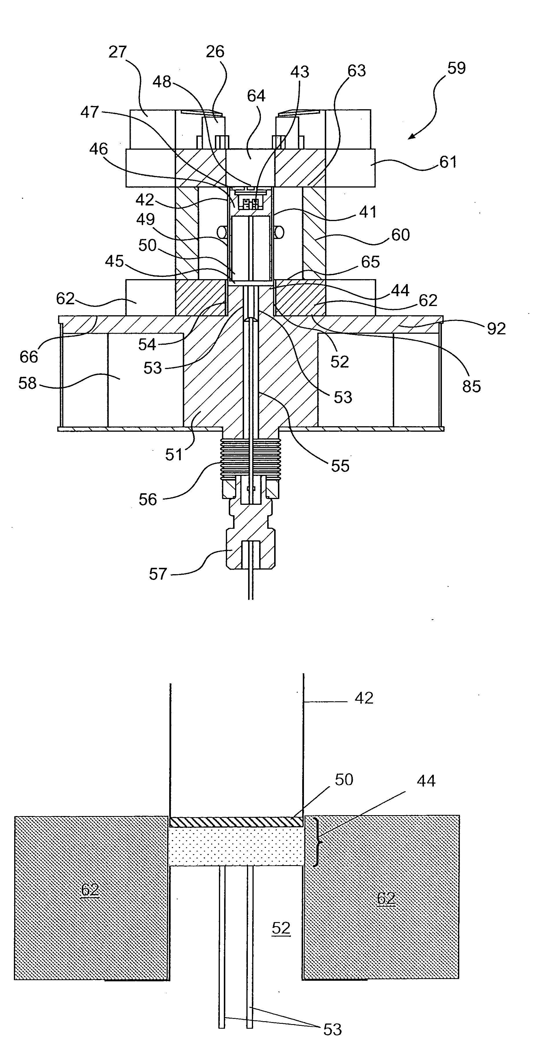
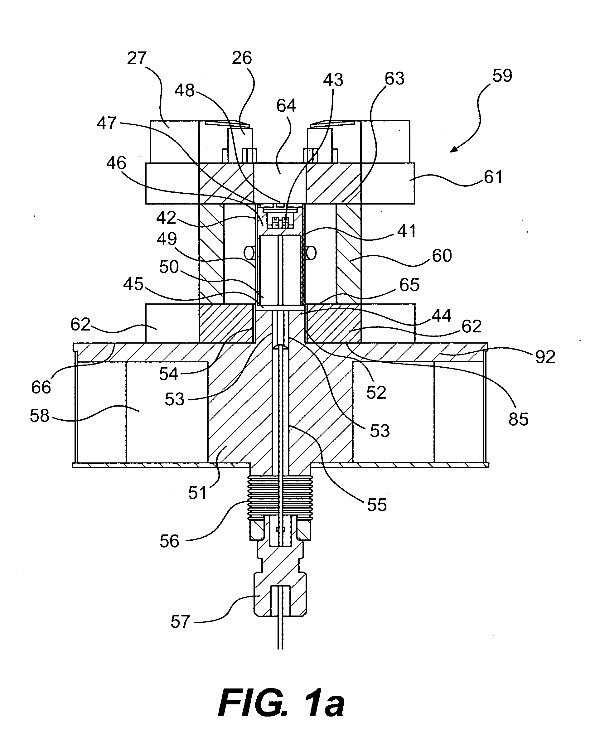
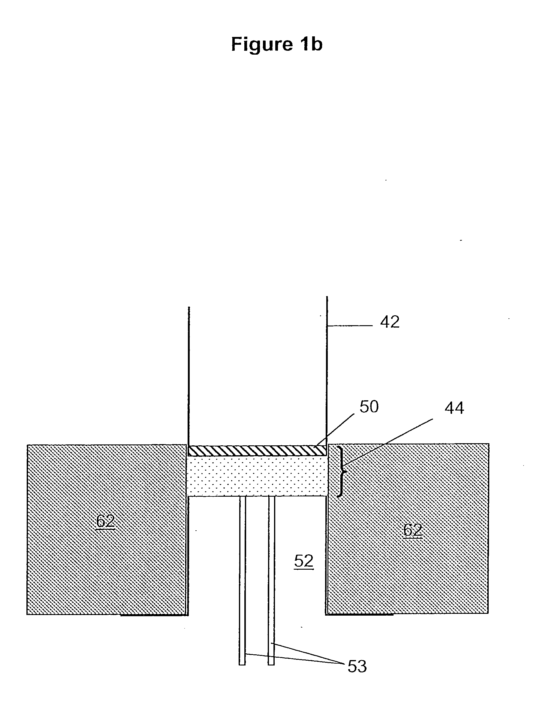
[0018]In order to clarify the present invention, embodiments of the present invention are discussed below with respect to FIGS. 1-5.

[0019]In one configuration of the present invention, a system for thermal measurement includes an infrared furnace used to heat a measuring assembly that incorporates a high thermal conductivity enclosure similar to that of a conventional DSC. The terms “system for thermal analysis,”“thermal measurement system, and “thermal analysis system” are used interchangeably herein to denote generally a system that is configured to measure the thermal properties of a sample, including DTA and DSC and related techniques. The enclosure reduces temperature difference errors that result from heat exchange between the sensor, sample containers and their surroundings.

[0020]In configurations of the present invention described in detail below, the exterior surface of the enclosure that houses the measurement assembly is an elongated circular cylinder that is equal in len...


PUM


Abstract

A thermal measurement apparatus and method for performing heat flux differential scanning calorimetry (DSC) is disclosed. A variable thermal resistor is used to couple a measurement assembly to a heat sink in the thermal measurement apparatus, such that samples can be rapidly heated and rapidly cooled. The apparatus can be configured with a highly conductive sample assembly enclosure. The enclosure can include a high emissivity coating. In one embodiment, the enclosure extends along a longitudinal direction that is about the same as that of an infrared lamp assembly used to heat the enclosure, thereby increasing the efficiency of heating the sample enclosure. In one configuration, the variable thermal resistor comprises a gap whose gas composition can be varied during a sample measurement to independently optimize sample heating and cooling rates.

Description

[0001]This application claims the benefit of U.S. Provisional Application Nos. 60 / 942,242 filed Jun. 6, 2007 and 60 / 942,245 filed on Jun. 6, 2007, which are herein incorporated by reference in their entirety.BACKGROUND[0002]1. Field of the Invention[0003]The present invention relates generally to apparatus and methods for materials property measurements performed during heating and cooling.[0004]Differential thermal analysis (DTA) and differential scanning calorimetry (DSC) can be performed at high sample heating rates, as described in U.S. Pat. No. 5,509,733 to Danley (“the '733 patent”), which discloses an “Infrared Heated Differential Thermal Analyzer” that allows both rapid heating and rapid cooling rates to be achieved. The '733 patent discloses the use of an infrared heat source to heat a differential thermal analysis (or potentially a differential scanning calorimetry) measuring assembly that is coupled to one or two heat sinks via one or two heat flow restricting elements th...

Claims


Application Information

Patent Timeline
IPC IPC(8): G01N25/20G01K7/16
CPCG01K17/00G01N25/4833
Inventor DANLEY, ROBERT L.
Owner WATERS TECH CORP
Why Eureka
Try Eureka