Particle Reduction Through Gas and Plasma Source Control

a technology of plasma source control and particle reduction, which is applied in the field of reducing particles, can solve the problems of particle adverse effects, and sometimes undesirable particles in the excited gas

Inactive Publication Date: 2008-12-11
MKS INSTR INC
View PDF14 Cites 50 Cited by
  • Summary
  • Abstract
  • Description
  • Claims
  • Application Information

AI Technical Summary

Benefits of technology

[0008]In some embodiments, the control loop controls an ignition sequence by igniting a plasma using a first gas, transitioning to a second gas, and transitioning to a final desired gas mixture while maintaining total gas flow rate above a minimum value. In some embodiments, the control loop controls a transition from a first gas mixture to a second gas mixture and a transition to a final desired gas mixture while maintaining total gas flow rate above a minimum value. In some embodiments, the system includes a showerhead or gas distribution system used to control gas input to the plasma chamber to protect the surface of the plasma chamber from plasma-surface interactions and gas-surface interactions in steady-state or transient operation of the remote plasma source.

Problems solved by technology

The charged particles in the excited gases, however, are sometimes undesirable because they interfere with the processes.
The particles adversely affect, for example, the process chamber walls and substrates located in the process chamber.

Method used


Image

  • Particle Reduction Through Gas and Plasma Source Control
  • Particle Reduction Through Gas and Plasma Source Control
  • Particle Reduction Through Gas and Plasma Source Control

Examples


Embodiment Construction

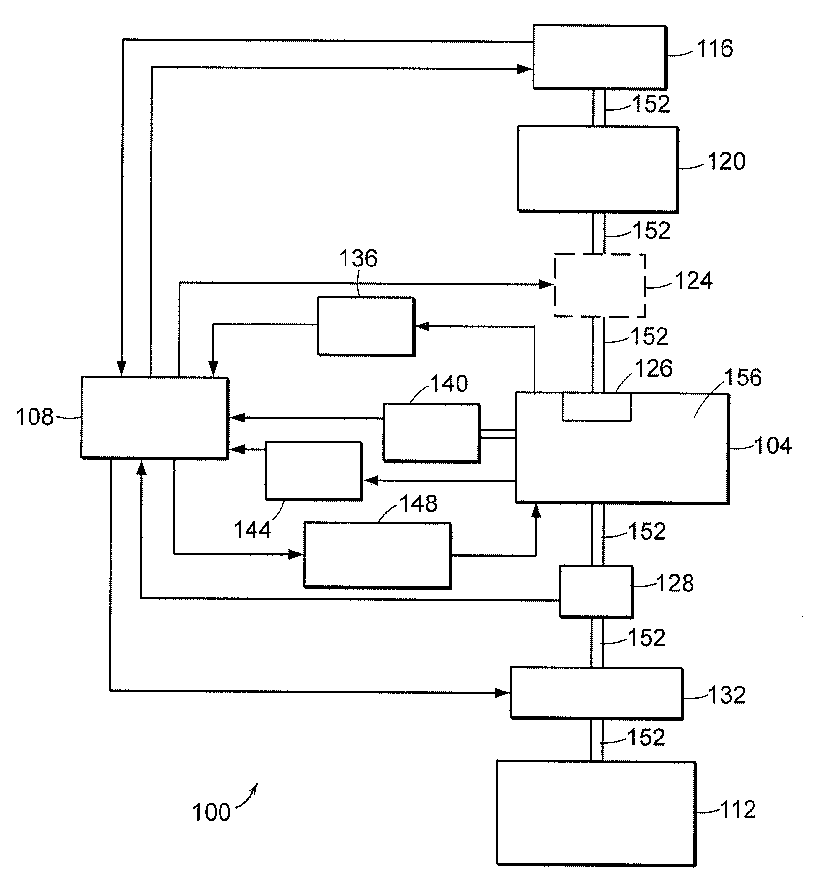
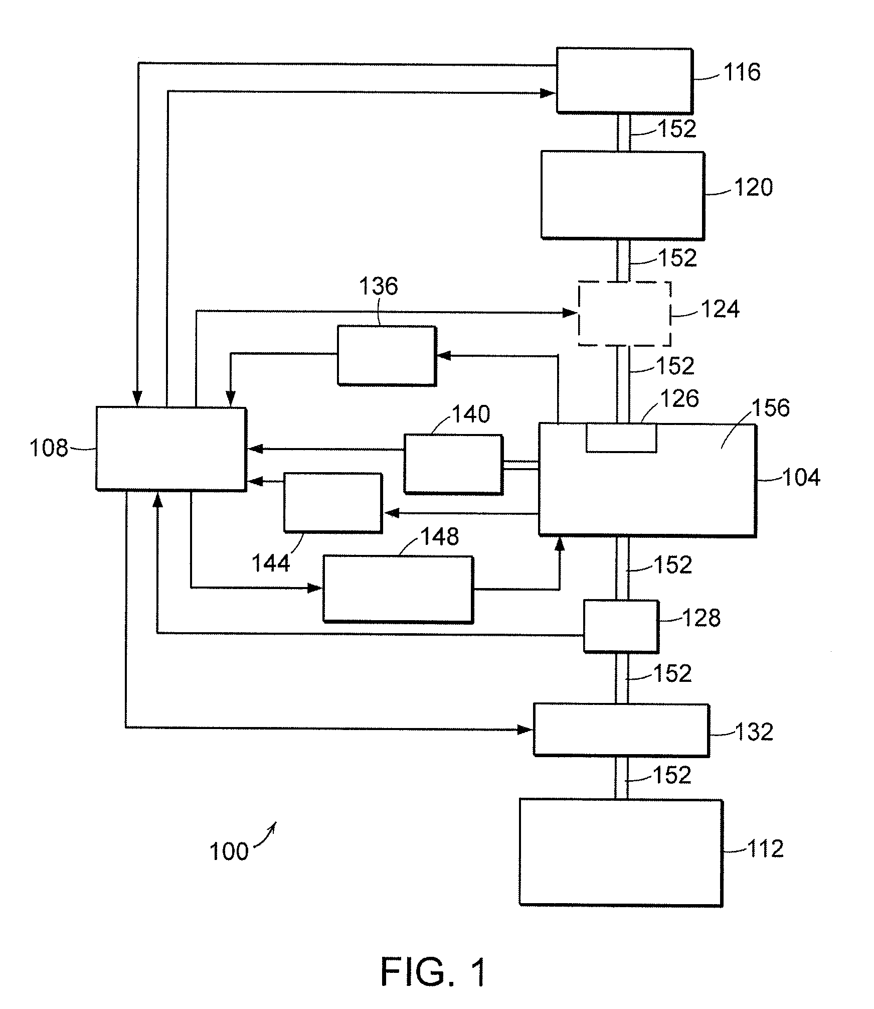
[0030]FIG. 1 is a schematic illustration of a plasma processing system 100 for producing excited gases that embodies the invention. The system 100 includes a remote plasma source 104 that is connected to a process chamber 112 by a gas pipeline 152. The system 100 includes a controller 108 (e.g., computer processor) that is coupled to various plasma processing components or subsystems that are used to operate the plasma processing system 100.

[0031]The system 100 includes a fluid supply system 116 that provides one or more gases or fluids to a chamber 152 of the remote plasma source 104 via the gas pipeline 152. The controller 108 provides a command signal to the fluid supply system 116 to vary properties of the gases or fluids provided by the fluid supply system 116 to the remote plasma source 104. In some embodiments, the fluid supply system 116 provides signals to the controller 108 that are used to, for example, monitor or alter the operation of the fluid supply system 116.

[0032]T...


PUM


Abstract

A system for producing excited gases for introduction to a semiconductor processing chamber. The system includes a plasma source for generating a plasma. The plasma source includes a plasma chamber and a gas inlet for receiving process gases from a gas source. A gas flow rate controller is coupled to the gas inlet for controlling an inlet flow rate of the process gases from the gas source to the plasma chamber via the gas inlet. The system includes a control loop for detecting a transition from a first process gas to a second process gas and for adjusting the inlet flow rate of the second process gas from about 0 sccm to about 10,000 sccm over a period of time greater than about 300 milliseconds to maintain transient heat flux loads applied by the plasma to an inner surface of the plasma chamber below a vaporization temperature of the plasma chamber.

Description

CROSS-REFERENCE TO RELATED APPLICATIONS[0001]This application claims the benefits of and priority to U.S. provisional patent application Ser. No. 60 / 942,343 filed on Jun. 6, 2007, the entire disclosure of which is herein incorporated by reference.FIELD OF THE INVENTION[0002]The present invention relates to methods and apparatus for reducing particles generated by a remote plasma source.BACKGROUND OF THE INVENTION[0003]Plasmas are often used to activate gases placing them in an excited state causing enhanced reactivity. The gases may be excited to produce dissociated gases containing ions, free radicals, atoms and molecules. Excited gases are used for numerous industrial and scientific applications, including processing solid materials such as semiconductor wafers and powders, other gases, and liquids. The parameters of the dissociated gas and conditions under which the dissociated gas interacts with a material to be processed by the system vary widely depending on the application. E...

Claims


Application Information

Patent Timeline
Patent Type & Authority Applications(United States)
IPC IPC(8): H05H1/24
CPCH01J37/32357H01J37/3244H01J37/32449H01J37/3299
Inventor ENTLEY, WILLIAM ROBERTCHEN, XINGSHAJII, ALIBAKHTARI, KAVEHCOWE, ANDREW
Owner MKS INSTR INC
Why Eureka
Try Eureka