Vapor vortex heat sink

a heat sink and vapor vortex technology, applied in the direction of machines/engines, mechanical and heating apparatus, and semiconductor/solid-state device details, can solve the problems of consuming inordinate energy for the task of extracting waste heat from cpus, affecting the efficiency of heat extraction, etc., to achieve power extraction and power generation.

Active Publication Date: 2009-10-01
MCCUTCHEN CO
View PDF42 Cites 53 Cited by
  • Summary
  • Abstract
  • Description
  • Claims
  • Application Information

AI Technical Summary

Benefits of technology

[0020]High shear in the radial vortex space below the pumping disk agitates the fluid against the heating surface and sweeps vapor away into radial vortex cores. Vapor does not form insulating bubbles on the surface as with pool boiling in a conventional heat pipe. Superheating of vapor is avoided by organized turbulence. Radial vortices in the narrow space, forced by disk rotation and sustained in coherence by the suction in the vapor space, provide sink flow

Problems solved by technology

Waste heat from digital signal processors (DSPs) and other high heat flux electronic components (collectively “CPUs” herein) degrades performance.
The task of extracting waste heat from CPUs consumes inordinate energy and is a major expense at data centers.
Adding fins to increase the surface area, and blowing air at the fins, cannot overcome the basic limitation of direct air cooling, which is its low heat flux.
If forcing is employed, to blow more molecules toward the surface, residence time of air molecules at the surface for heat transfer will be short.
The problem is that vapor from the heated fin or other sur

Method used


Image

  • Vapor vortex heat sink
  • Vapor vortex heat sink
  • Vapor vortex heat sink

Examples


Embodiment Construction

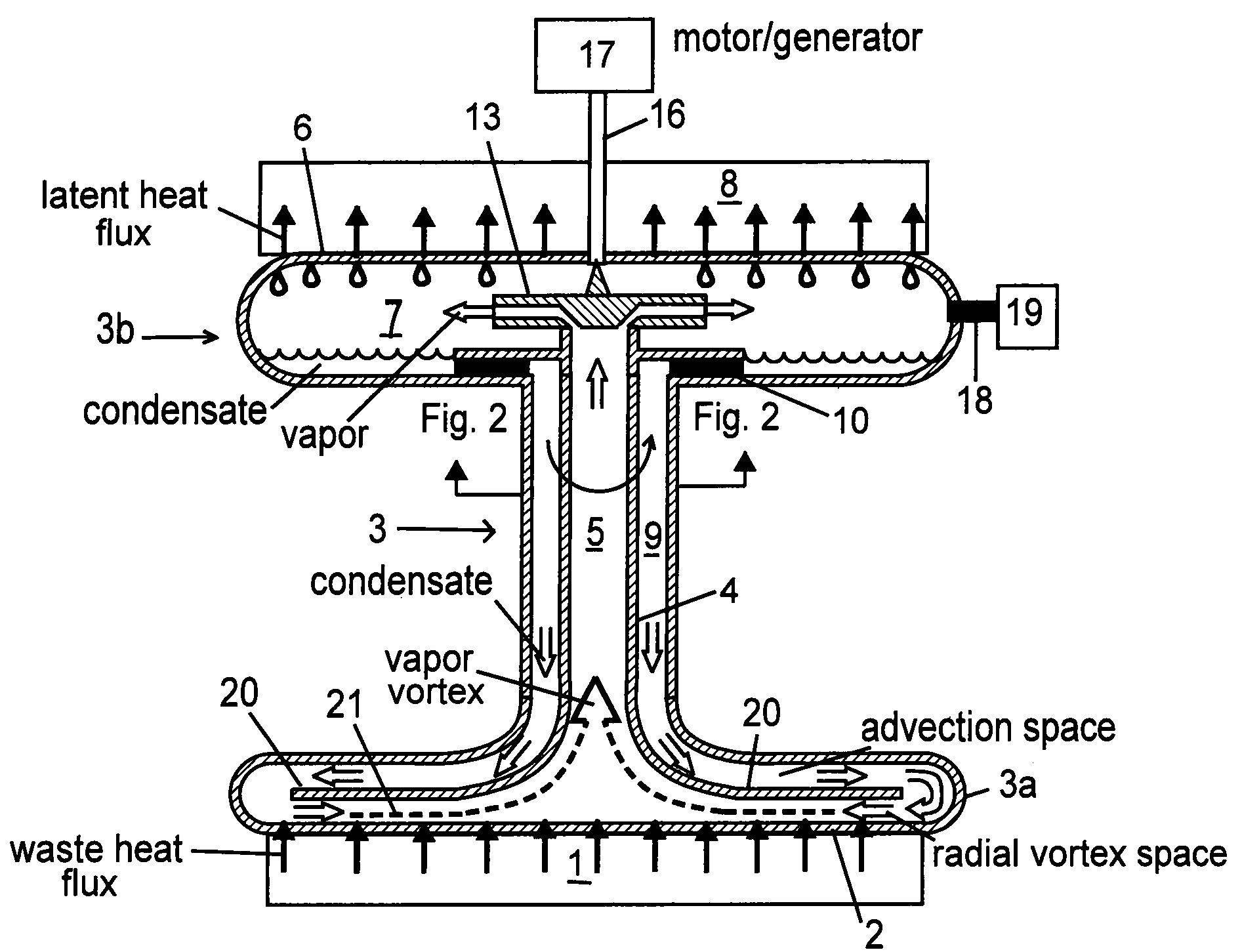
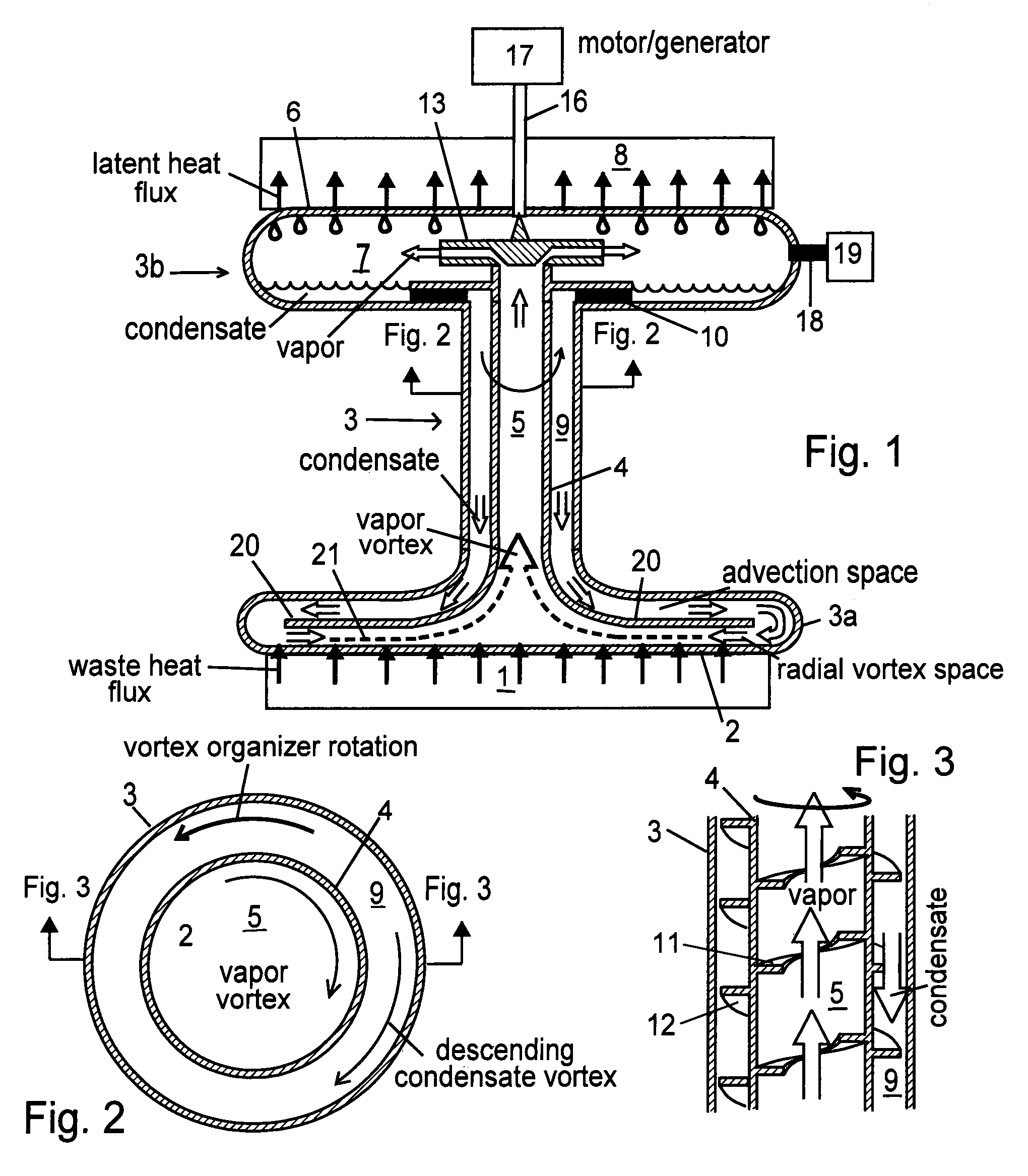
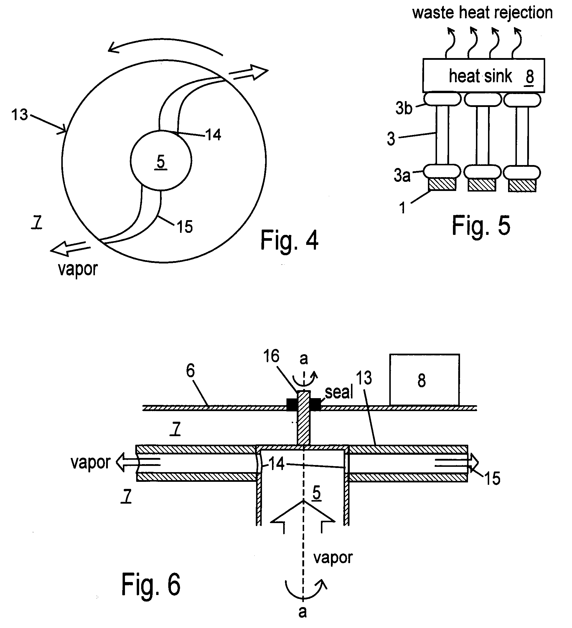
[0071]FIG. 1 shows a cross-sectional schematic view of the preferred embodiment of the present invention. A heat source 1 such as a metal surface communicating thermally with a CPU communicates thermally with a heating surface 2 which is part of a hermetic casing 3, the casing having an evaporating end 3a and a condensing end 3b. The condensing end 3b comprises a condensing surface 6 in thermal communication with a conventional heat sink 8. The heat sink 8 could be a chiller or other high cooling power means for heat rejection to the environment known to the art of refrigeration. Or it could be a fin and tube condenser or a pool or pipe of water. Many other conventional heat sinks are known to the art and might be suitable as a heat sink 8, depending on the waste heat extraction application. The heat sink 8 is sized for the cooling power, conventionally measured in tons of refrigeration (1 ton of refrigeration=3517 watts), required by the heat load it serves. A plurality of vapor vo...


PUM


Abstract

A hermetic Rankine cycle in a sealed casing powers an internal centrifugal condensate pump with an internal vapor turbine during forced convective heat transfer between a heat source and a heat sink. No work is imported into the cycle during operation. A centrifugal pumping disk shears the working fluid against a heating surface, sweeping evolving vapor into radial vortices which provide sink flow conduits to a vapor space at the center of the cylindrical turbine. Convective mass flow through the vapor space to the condensing end of the casing spins the turbine and the centrifugal pumping disk which is connected to it. Vapor is continuously swept from the heating surface, so bubbles do not form and superheat while blocking heat flux into liquid working fluid. Vapor is sucked through the radial vortices into the central vapor space and into the condensing end of the casing along the low pressure gradients in vortex cores established by cooling power. A high heat flux surface is thereby thermally connected to a conventional heat sink having high cooling power, for maximal heat extraction at data centers or other heat sources. Vapor vortices organize counterflow of vapor and condensate in a continuous mass flow cycle, and extract work from heat. Organic working fluids can be used in the casing to make even low temperature waste heat a power source.

Description

APPLICATION HISTORY[0001]The applicants claim the benefit of U.S. Provisional Patent Applications 61 / 041,110 filed Mar. 31, 2008 and 61 / 043,919 filed Apr. 10, 2008.BACKGROUND OF THE INVENTION[0002]This invention relates to waste heat extraction by forced convection boiling, to means for preventing vapor bubbles at heating surfaces, and to organic Rankine cycles for electric power generation from waste heat.Chip Cooling:[0003]Waste heat from digital signal processors (DSPs) and other high heat flux electronic components (collectively “CPUs” herein) degrades performance. The task of extracting waste heat from CPUs consumes inordinate energy and is a major expense at data centers.[0004]The CPU's surface area is small and the heat flux through that small surface area must be high to get rid of the heat. Adding fins to increase the surface area, and blowing air at the fins, cannot overcome the basic limitation of direct air cooling, which is its low heat flux. The diffuse distribution of...

Claims


Application Information

Patent Timeline
IPC IPC(8): F28D15/00
CPCF28D15/0233F28D15/025F28D15/0266F28D2015/0291H01L23/427H01L2924/0002F28F2250/08F01K25/08H01L2924/00
Inventor MCCUTCHEN, WILMOT H.MCCUTCHEN, DAVID J.
Owner MCCUTCHEN CO
Why Eureka
Try Eureka