Medical connector

a technology of medical devices and connectors, applied in the field of medical devices, can solve the problems of reducing manufacturing costs, increasing manufacturing costs, and difficult control of deformed parts, and stably fixing disc valves

Inactive Publication Date: 2008-12-11
NIPRO CORP
View PDF12 Cites 36 Cited by
  • Summary
  • Abstract
  • Description
  • Claims
  • Application Information

AI Technical Summary

Benefits of technology

[0019]In the medical connector of the invention with such a configuration, since the outer diameter of the connector itself does not increase, the medical connector can be directly connected to the luer lock connector, and thus it is not necessary to use the exclusive connector.

Problems solved by technology

Although the mechanical valve-type connector is formed into a cylindrical shape so as to be connected to the luer lock connector, manufacturing cost increases because the shape of the rubber valve is complicated.
Meanwhile, the split septum-type connector is a connector formed by a housing to which the disc shaped valve is fixed, and manufacturing cost decreases because the shape is simple.
However, in such a fixation method, it is difficult to control the deformed part and to stably fix the disc shaped valve.
When the stepped portion is formed between the upper surfaces of the disc shaped valve and the housing, it is not possible to sufficiently disinfect the upper surfaces before using the connector, and thus germs may be mixed with the fluid in the infusion route.
With such a configuration, although a stepped portion is not formed on the upper surface of the connector, the shape becomes complicated because the number of components increases.
In addition, since the outer diameter of the connector itself becomes large, it is not possible to carry out the connection operation of the luer lock connector in which a female screw is formed on the outer circumference of the male luer.
Accordingly, when a connection operation of the luer lock connector is carried out, it is necessary to use an exclusive connector, thereby deteriorating the merit that the shape of the split septum-type connector is simple.

Method used


Image

  • Medical connector
  • Medical connector
  • Medical connector

Examples


Embodiment Construction

[0025]Hereinafter, an exemplary embodiment of the invention will be described with reference to the accompanying drawings, but the invention is not limited thereto.

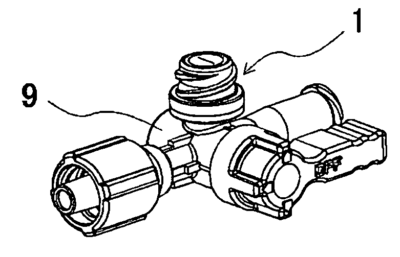
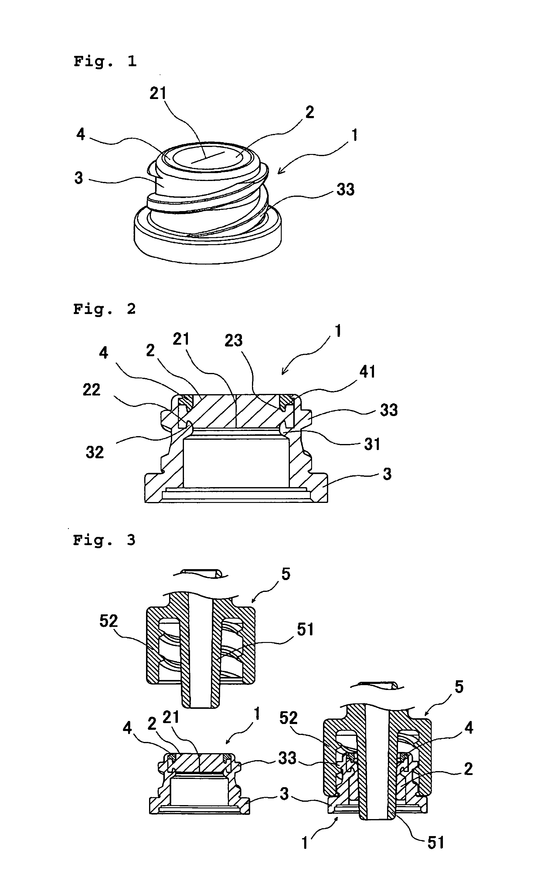
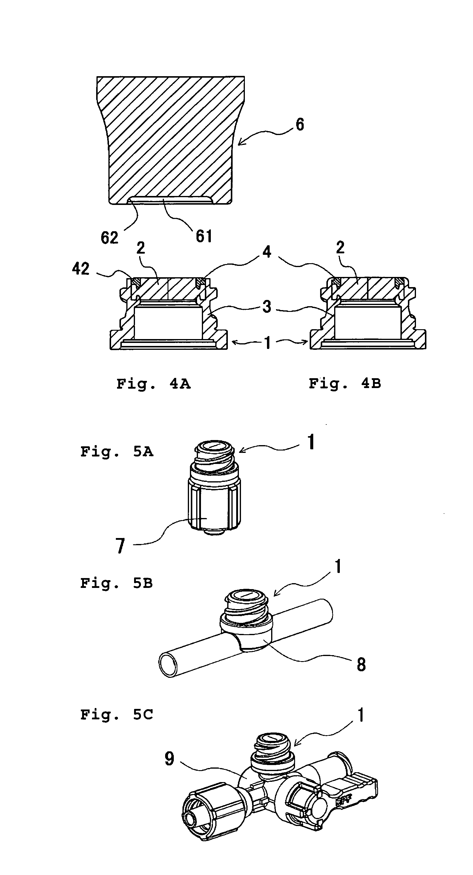
[0026]FIG. 1 is a perspective view illustrating a medical connector according to an embodiment of the invention. FIG. 2 is a longitudinal sectional view illustrating the medical connector shown in FIG. 1. FIG. 3 is a sectional view illustrating a state where a luer lock connector is connected to the medical connector according to the invention. FIGS. 4A and 4B are explanatory views illustrating a method of forming the medical connector according to the invention. FIGS. 5A, 5B, and 5C are perspective views illustrating usage examples of the medical connector according to the invention.

[0027]As shown in FIGS. 1 and 2, a medical connector 1 according to the invention includes a disc shaped valve member 2 having a slit 21 formed at the center thereof, a housing 3 which sandwiches a circumferential edge of the valve member 2, ...


PUM

PropertyMeasurementUnit
heightaaaaaaaaaa
heightaaaaaaaaaa
outer diameteraaaaaaaaaa

Abstract

A medical connector capable of allowing, in which a stepped portion is not formed between upper surfaces of a valve and a housing, includes a disc shaped valve member which has a slit formed at a center portion thereof; a housing with a substantially cylindrical shape which sandwiches a circumferential edge portion of the valve member; and an annular ring member which is disposed on an upper circumferential edge of the valve member other than the center portion thereof, wherein the housing has a pedestal which is formed on an inner circumferential surface thereof so as to protrude inward, the valve member being placed on the pedestal, and wherein the valve member is fixed to the inside of the housing by allowing the ring member and the housing to be joined to each other by a swaging process after the valve member is placed on the pedestal in the housing.

Description

TECHNICAL FIELD OF THE INVENTION[0001]The present invention relates to a medical connector capable of allowing a connection tool with a luer lock connector to be connected thereto upon mixing / injecting medicinal solution into an infusion route, or path or drawing out body fluid therethrough.BACKGROUND OF THE INVENTION[0002]In general, a medical connector, to which a medical connection tool such as a syringe or a luer lock connector can be connected, is disposed in an infusion route in order to mix and inject medicinal solution into the infusion route or to draw out body fluid therethrough. As the medical connector, there are known a cylindrical connector called a mechanical valve type in which a bellows cylindrical rubber valve with a spike built in the center portion thereof (see, for example, Japanese Patent Laid-Open No. 7-505064 or Japanese Patent Laid-Open No. 10-323397) and a connector called a split septum type which comprises a housing provided with a disc shaped valve (see,...

Claims


Application Information

Patent Timeline
Patent Type & Authority Applications(United States)
IPC IPC(8): A61M25/18
CPCA61M39/045A61M39/10A61M39/26A61M2039/1033Y10T29/49826A61M2039/1083A61M2039/1088A61M39/22A61M2039/1072
Inventor MASUDA, TAKUYAISHIZAKI, AKIHIKO
Owner NIPRO CORP
Why Eureka
Try Eureka