Method of manufacturing an interconnect device which forms a heat sink and electrical connections between a heat generating device and a power source

a technology of interconnection device and heat sink, which is applied in contact member manufacturing, semiconductor devices for light sources, light and heating apparatus, etc., can solve the problems of reducing the performance and life of not only the device itself, but of the entire system, and the surface area of two-dimensional aluminum core boards is limited to dissipate hea

Inactive Publication Date: 2008-12-18
MOLEX INC
View PDF75 Cites 38 Cited by
  • Summary
  • Abstract
  • Description
  • Claims
  • Application Information

AI Technical Summary

Problems solved by technology

Furthermore, because of the small size of LED lights, LED lights can be packaged in ways that incandescent and fluorescent lighting cannot be packaged.
In the electronics industry, heat is a significant problem.
This, in turn, may reduce the performance and life of not only the devices themselves, but of the entire system.
Therefore, one of the primary challenges in fully commercializing LED lighting is the solution to the thermal management of the heat generated by LED lighting in a cost effective manner.
Two dimensional aluminum core boards have limited surface area to dissipate heat.
In addition, the LED lights cannot be easily interchanged to either replace defective units or to change the product color.
Heat management in electrical devices that are becoming smaller, lighter, and more compact is an ever increasing challenge.
Because the heat sinks are made of metal, the heat sinks are often heavy.
These values are predefined and can only be improved or modified by the manufacturers of the LEDs.
Many of these techniques are complicated and require many steps to produce the end product, resulting in a very expensive and uneconomic process.
Some of the other techniques that showed promise to be cost effective, had other limitations with respect to lead times for tooling or limitations on resolution.
Furthermore, this process could not be used for decorative parts because the entire surface of the product needed to be etched, making the surfaces non-cosmetic.
It has some limitations in that it is a line of sight process.
This makes plated through-holes more difficult to manufacture and any plating on surfaces that is not on a line of sight plane requires that the part be moved.
Furthermore, the processing time under the laser is an additional cost that the two shot process does not have.
The two shot process limitations include higher cost tooling, longer lead-time prototypes, and line / space limitations.

Method used


Image

  • Method of manufacturing an interconnect device which forms a heat sink and electrical connections between a heat generating device and a power source
  • Method of manufacturing an interconnect device which forms a heat sink and electrical connections between a heat generating device and a power source
  • Method of manufacturing an interconnect device which forms a heat sink and electrical connections between a heat generating device and a power source

Examples


first embodiment

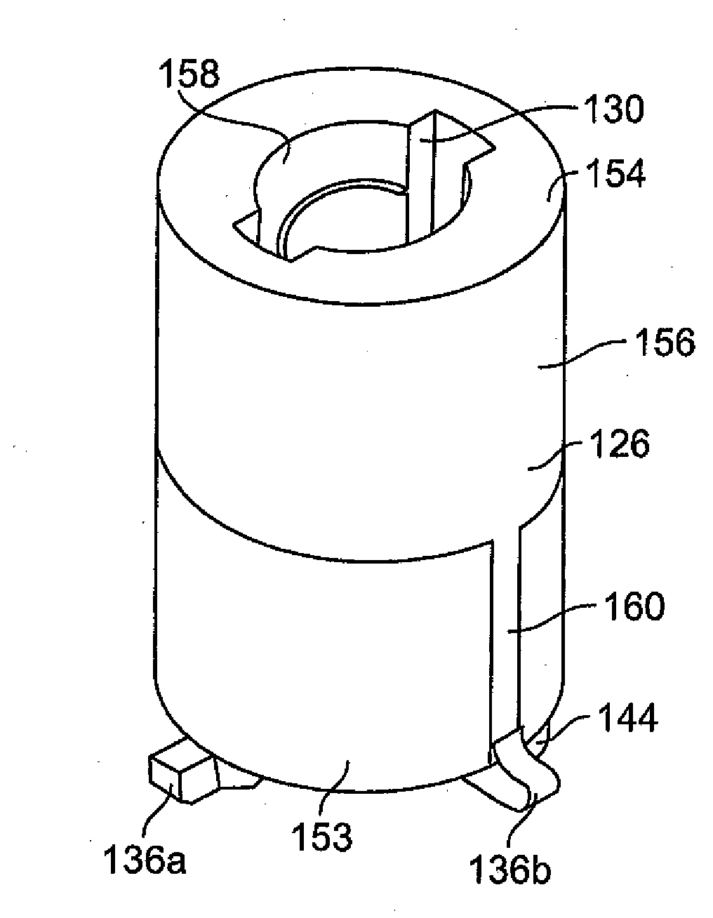
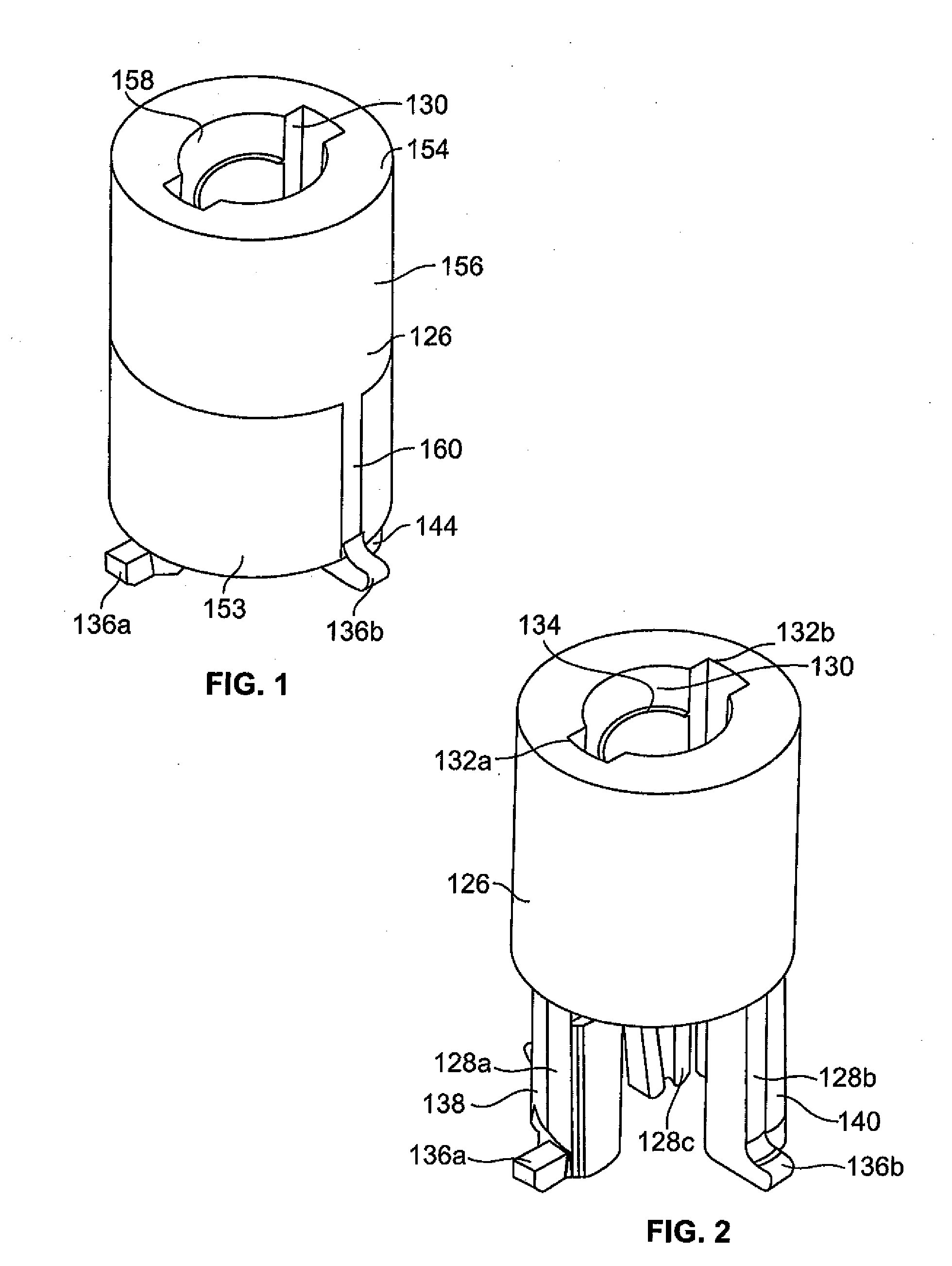
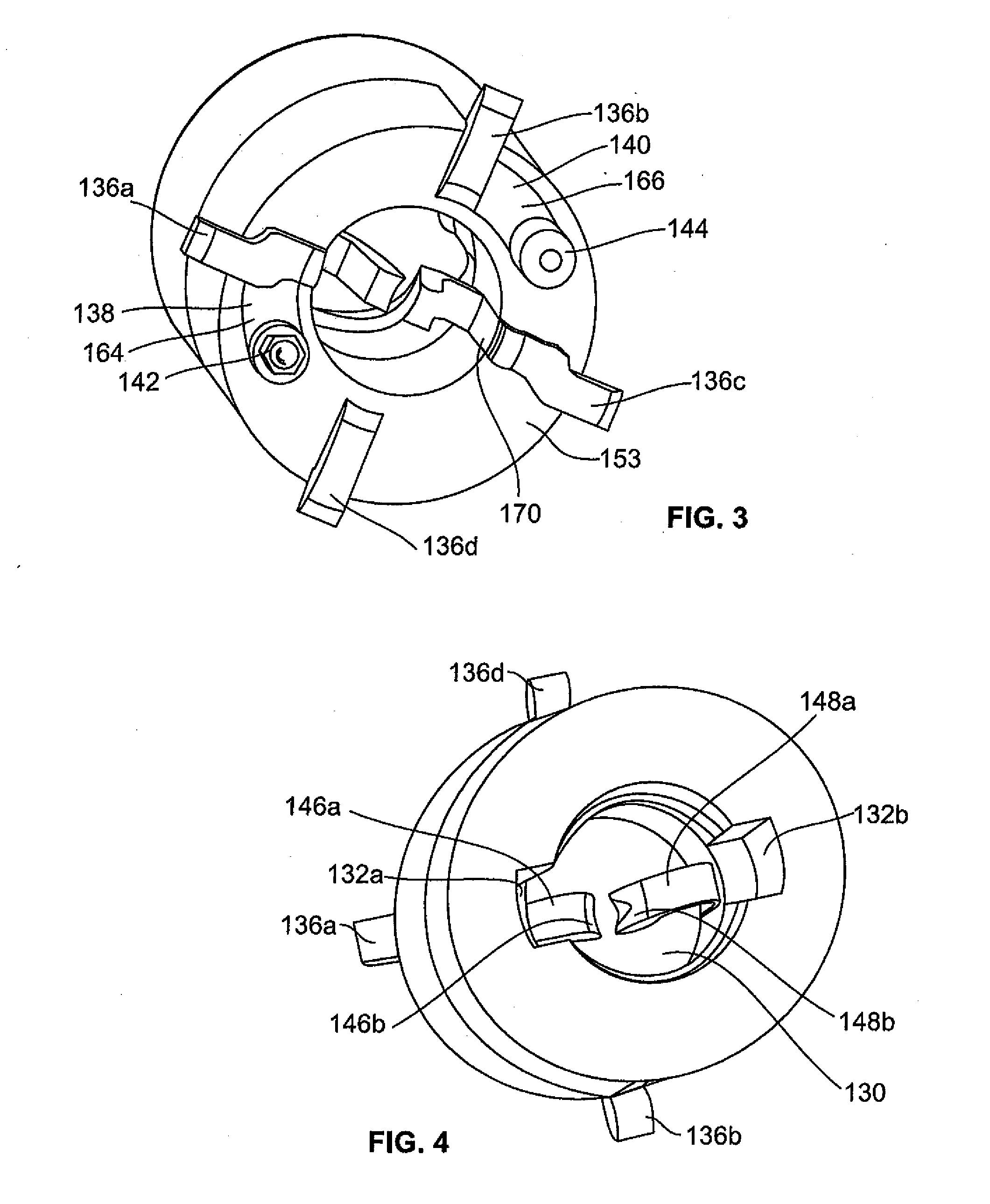
[0121]Attention is invited to the interconnect device 120 which is shown in FIGS. 1-8. As shown in FIG. 2, the first shot creates a base member which includes a base 126 having a plurality of legs 128a, 128b, 128c, 128d extending from a lower end thereof. The first shot is formed of a plateable thermoplastic material that can be metalized because of a palladium catalyst added to the plastic. The base 126 is generally cylindrical and has a cylindrical central passageway 130 extending from an upper end to the lower end therethrough. The upper end of the passageway 130 has diametrically opposed recesses 132a, 132b which radiate outwardly from the passageway 130. A thread form 134 is provided in the passageway 130 so that the LED device 22 can be mated with the base 126.

[0122]Each leg 128a, 128b, 128c, 128d is generally vertical and extends downwardly from the base 126. A generally horizontal foot 136a, 136b, 136c, 136d extends perpendicularly from the respective leg 128a, 128b, 128c, 1...

second embodiment

[0132]Attention is now invited to the interconnect device 220 which incorporates the features of the present invention which is shown in FIGS. 9-13.

[0133]The first shot creates a base member which includes a base 226 having a plurality of legs 228a, 228b, 228c, 228d extending from a lower end at the corners thereof. The first shot is formed of a plateable thermoplastic material which can be metalized because of a palladium catalyst added to the plastic. Each leg 228a, 228b, 228c, 228d terminates in a foot. If desired, a generally horizontal foot such as that shown in the first embodiment can be provided at the lower end of each leg 228a, 228b, 228c, 228d.

[0134]The base 226 includes a planar portion 230 which has a plurality of vias 232 provided therethrough. As shown, the vias 232 are provided in rows and columns, however, this is not a required configuration. Each leg 228a, 228b, 228c, 228d is generally vertical. Two of the legs 228a, 228d extend downwardly from the front two corn...

third embodiment

[0145]Attention is invited to the interconnect device 320 which incorporates the features of the present invention which is shown in FIGS. 14-18.

[0146]The first shot creates a base member which includes a base 326 having a plurality of legs 328a, 328b, 328c, 328d extending from a lower end at the corners thereof. The first shot is formed of a plateable thermoplastic material which can be metalized because of a palladium catalyst added to the plastic. Each leg 328a, 328b, 328c, 328d terminates in a foot. If desired, a generally horizontal foot such as that shown in the first embodiment can be provided at the lower end of each leg 328a, 328b, 328c, 328d.

[0147]The base 326 includes a planar portion 330 which has a plurality of vias 332 provided therethrough. As shown, the vias 332 are provided in rows and columns, however, this is not a required configuration. A first side wall 334 extends upwardly from the planar portion 330 along one edge thereof, a second side wall 336 extends upwa...


PUM

PropertyMeasurementUnit
temperatureaaaaaaaaaa
colorsaaaaaaaaaa
heat dissipatingaaaaaaaaaa

Abstract

An interconnect device is used to mate a heat generating device to a power source. Plated components are provided on the interconnect device to provide a heat sink function for the heat generating device when the heat generating device is connected to the interconnect device, and to provide an electrical path between the heat generating device and the power source. A method of manufacturing same is also disclosed.

Description

[0001]This application claims the domestic benefit of U.S. Provisional Application Ser. No. 60 / 931,878 filed on May 25, 2007, U.S. Provisional Application Ser. No. 61 / 008,655 filed on Dec. 21, 2007, and U.S. Provisional Application Ser. No. 61 / 038,469 filed on Mar. 21, 2008, which disclosures are hereby incorporated by reference.FIELD OF THE INVENTION[0002]This invention is generally directed to an interconnect device for housing heat generating devices, such as an LED device, resistors and capacitors and the like. The interconnect device forms a connection between heat generating devices and a power source.BACKGROUND OF THE INVENTION[0003]LED lighting is becoming very important in the lighting industry. LED lighting has significant advantages over both incandescent and fluorescent lighting. LED lighting is more energy efficient than incandescent bulbs and LED lighting does not have the cold temperature use and mercury issues of the fluorescent bulbs. Furthermore, because of the sma...

Claims


Application Information

Patent Timeline
Patent Type & Authority Applications(United States)
IPC IPC(8): H01R43/16
CPCF21Y2101/02Y10T29/49155H05K3/301H05K2201/10106H05K2201/10325F21V19/0015F21V19/042F21K9/13F21V29/74F21V29/773F21V29/80F21V29/83Y10T29/49204Y10T29/49208Y10T29/49222H05K1/0203F21K9/23F21Y2115/10F21V19/04
Inventor ZADEREJ, VICTORO'CONNOR, KEVINMANLAPAZ, CHARLIEHAGAN, TIMOTHYRAMEY, SAMUEL C.
Owner MOLEX INC
Why Eureka
Try Eureka