Air flow measuring device

a technology of air flow and measuring device, which is applied in the direction of engine testing, structural/machine measurement, instruments, etc., can solve the problem of easy damage to the measuring element, and achieve the effect of reducing the damage to the flow amount sensor

Inactive Publication Date: 2008-12-18
DENSO CORP
View PDF20 Cites 10 Cited by
  • Summary
  • Abstract
  • Description
  • Claims
  • Application Information

AI Technical Summary

Benefits of technology

[0008]In view of the foregoing problems, it is an object of the present invention to provide an air flow measuring device, which can effectively reduce a damage to a flow amount sensor due to a collision of dust.

Problems solved by technology

In particular, when a thin film-like measuring element is used in the flow amount sensor 140, the measuring element is easily damaged by the collision of the dust.

Method used


Image

  • Air flow measuring device
  • Air flow measuring device
  • Air flow measuring device

Examples


first embodiment

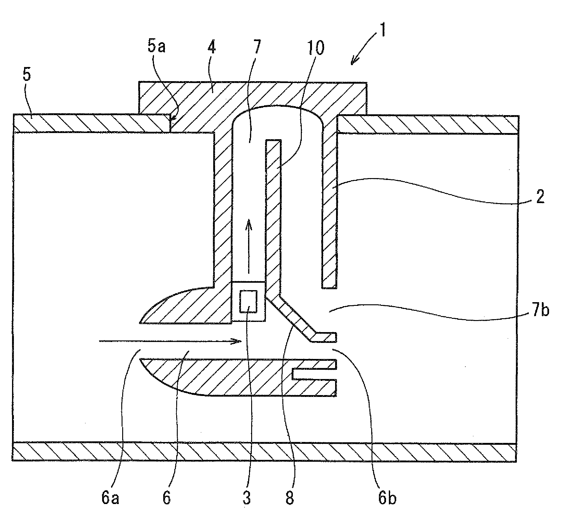
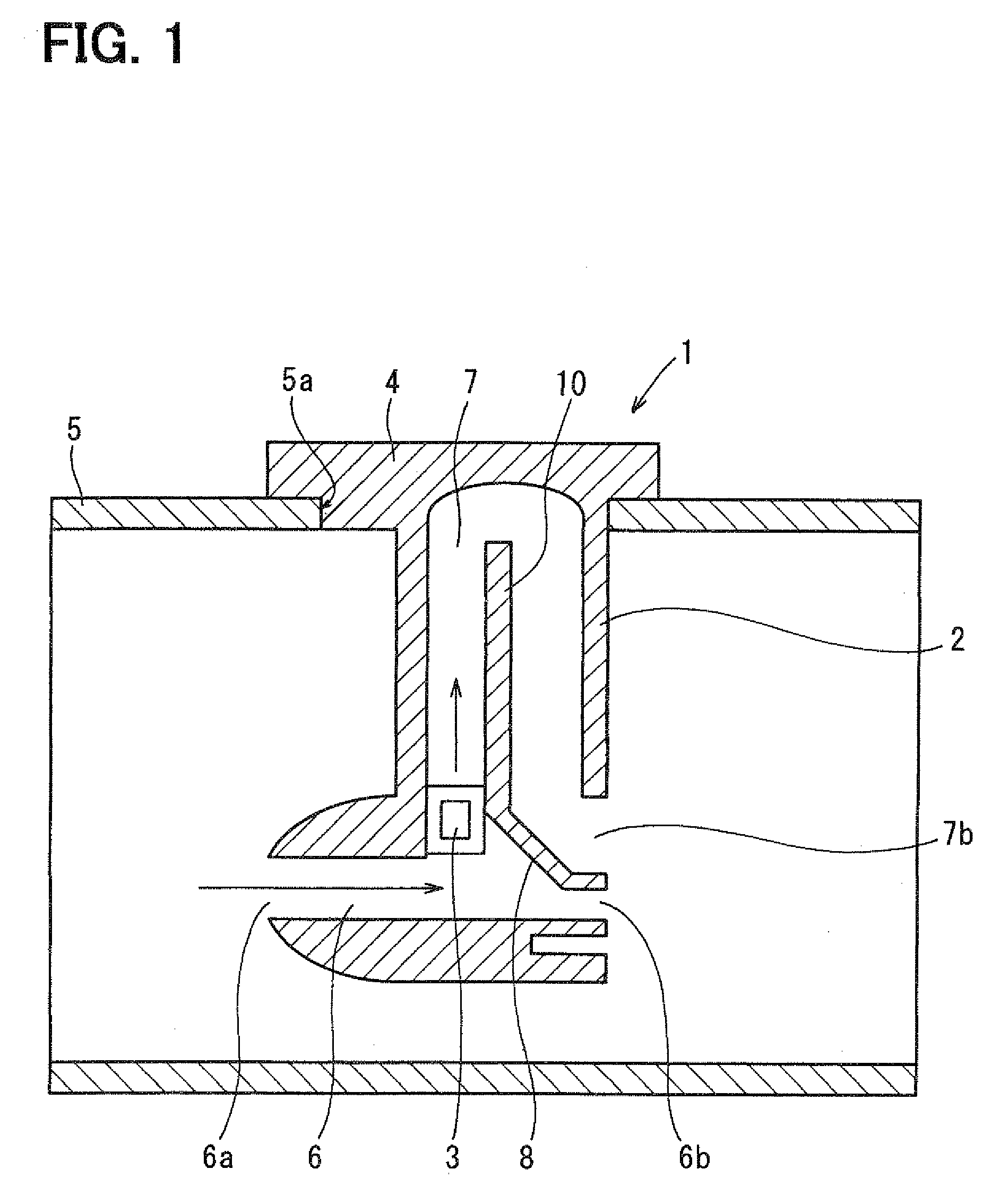
[0023]An air flow measuring device 1 of a first embodiment will be now described with referent to FIGS. 1 and 2. For example, the air flow measuring device 1 can be used as an air flow meter for measuring a flow amount of intake air in an internal combustion engine for a vehicle. The air flow measuring device 1 includes a sensor body 2, a flow amount sensor 3 and a circular module 4.

[0024]The sensor body 2 is inserted into an interior of an intake air duct 5 of the engine. Air flows into an intake air port of the engine through the intake air duct 5. The intake air duct 5 has an attachment hole portion 5a into which the sensor body 2 is fitted after the sensor body 2 inserted into the interior of the intake air duct 5. The sensor body 2 is provided with a first sub-passage 6 into which a part of air flowing in the intake air duct 5 is introduced, and a second sub-passage 7 into which a part of air flowing in the first sub-passage 6 is introduced.

[0025]In the example of FIG. 1, air f...

second embodiment

[0039]A second embodiment of the present invention will be described with reference to FIGS. 3A and 3B. In the second embodiment, the structure of the first sub-passage 6, for forming the throttle portion at a downstream side position in the first sub-passage 6, is made different from that of the above-described first embodiment.

[0040]In the second embodiment, a first radial direction of the first sub-passage 6 indicates the top-bottom direction of FIG. 3A, and a second radial direction of the first sub-passage 6 indicates a radial direction perpendicular to the top-bottom direction shown in FIG. 3A. FIG. 3B is a cross-sectional view taken along the line IIIB-IIIB of FIG. 3A, and shows the radial dimension of the first sub-passage 6 in the second radial direction.

[0041]As shown in FIG. 3B, a pair of wall portions 9 are provided in the first sub-passage 6 to gradually reduce a passage sectional dimension in the second radial direction as toward the outlet 6b. The wall portions 9 are ...


PUM


Abstract

An air flow measuring device includes a first sub-passage portion configured to introduce therein a part of air flowing in an interior of a duct, a passage-area reducing portion provided in the first sub-passage portion to gradually reduce a passage sectional area of the first sub-passage portion as toward an outlet of the first sub-passage portion, and a second sub-passage portion branched from the first sub-passage portion at an upstream side of the passage-area reducing portion in a flow direction of air flowing in the first sub-passage portion. The second sub-passage portion is configured to introduce therein a part of air flowing in the first sub-passage portion. Furthermore, a flow amount sensor is located at an inlet of the second sub-passage portion, at which the second sub-passage portion is branched from the first sub-passage portion, to measure a flow amount of air flowing in the second sub-passage portion.

Description

CROSS REFERENCE TO RELATED APPLICATION[0001]This application is based on Japanese Patent Application No. 2007-157362 filed on Jun. 14, 2007, the contents of which are incorporated herein by reference in its entirety.BACKGROUND OF THE INVENTION[0002]1. Field of the Invention[0003]The present invention relates to an air flow measuring device having a flow amount sensor for measuring a flow amount of air.[0004]2. Description of the Related Art[0005]An air flow measuring device described in U.S. Pat. No. 7,089,788 (corresponding to JP 2005-140753A) is used as an air flow meter for measuring a flow amount of intake air flowing into an internal combustion engine. As shown in FIG. 4, the air flow measuring device includes a sensor body 110 disposed in an intake air passage 100 of the internal combustion engine. The sensor body 110 is provided with a first sub-passage 120 into which a part of air flowing in the intake air passage 100 is introduced, and a second sub-passage 130 into which a ...

Claims


Application Information

Patent Timeline
Patent Type & Authority Applications(United States)
IPC IPC(8): G01M15/00
CPCG01F1/6842G01F5/00
Inventor KITAHARA, NOBORU
Owner DENSO CORP
Why Eureka
Try Eureka