Device for Reducing Vibrations and Sounds

a technology applied in the direction of vibration dampers, springs/dampers, dampers with inertia effect, etc., can solve the problems of vibration and sound, vibration and sound, known passive vibration absorber elements giving poor effects, etc., and achieve the effect of simple vibration absorber

Inactive Publication Date: 2008-12-18
A2 ACOUSTICS
View PDF13 Cites 6 Cited by
  • Summary
  • Abstract
  • Description
  • Claims
  • Application Information

AI Technical Summary

Benefits of technology

[0006]The object of the invention is to provide a simple vibration absorber which is arranged to operate against different frequencies.

Problems solved by technology

This motor speed results in vibrations and sounds with a relatively well defined fundamental frequency.
These various motor speeds result in vibrations and sounds with two or several relatively well defined fundamental frequencies.
The known passive vibration absorber elements give a poor effect when several motor speeds are used since they merely operate against one frequency.
However, this increases the required quantity of absorber elements in an undesired manner.
Furthermore, the absorber elements which do not respond to the actual frequency may instead result in an amplification of vibrations and sounds.
Furthermore, extensive wiring for current supply, and control equipment for the adjustment of the absorber elements are required.

Method used


Image

  • Device for Reducing Vibrations and Sounds
  • Device for Reducing Vibrations and Sounds
  • Device for Reducing Vibrations and Sounds

Examples


first embodiment

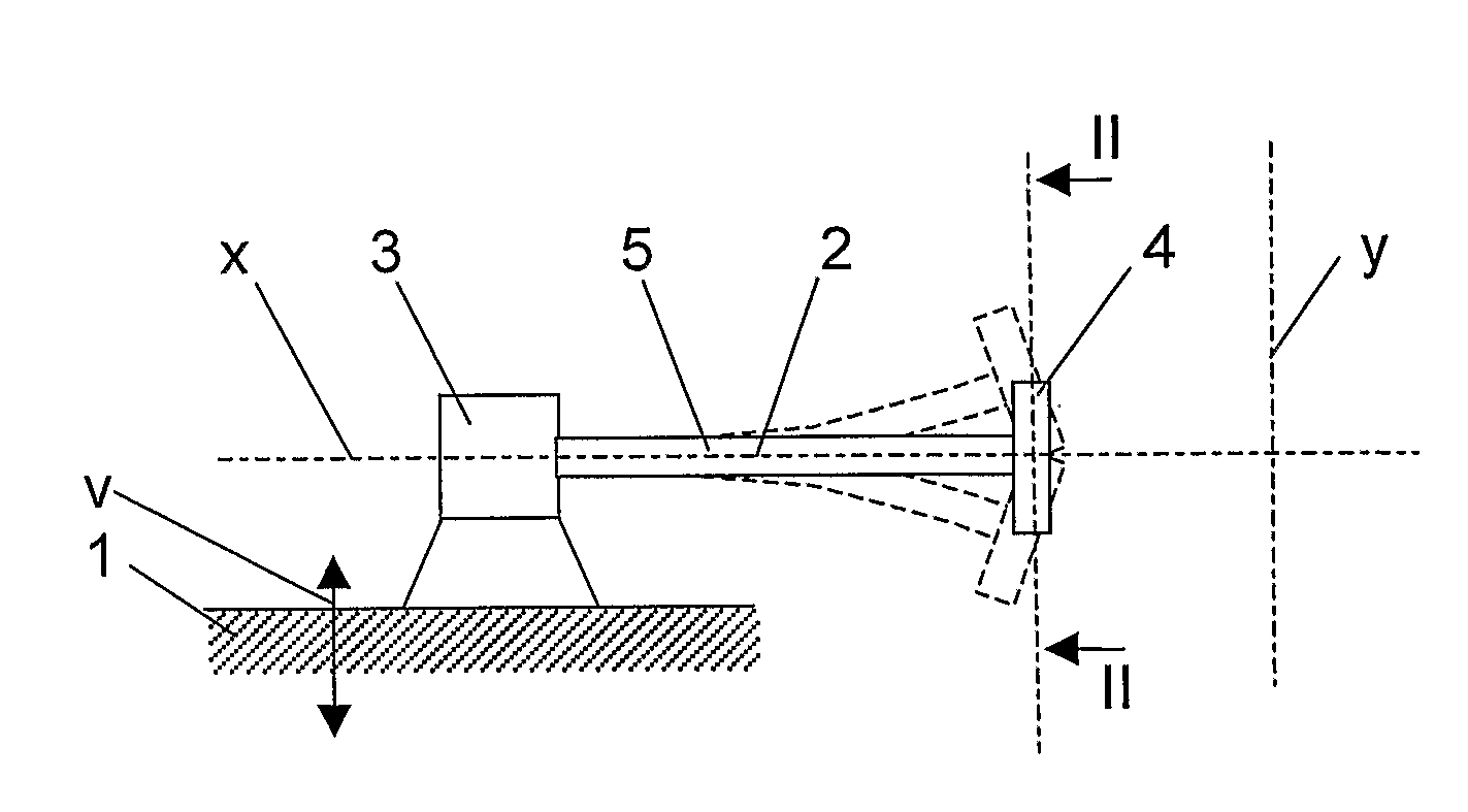
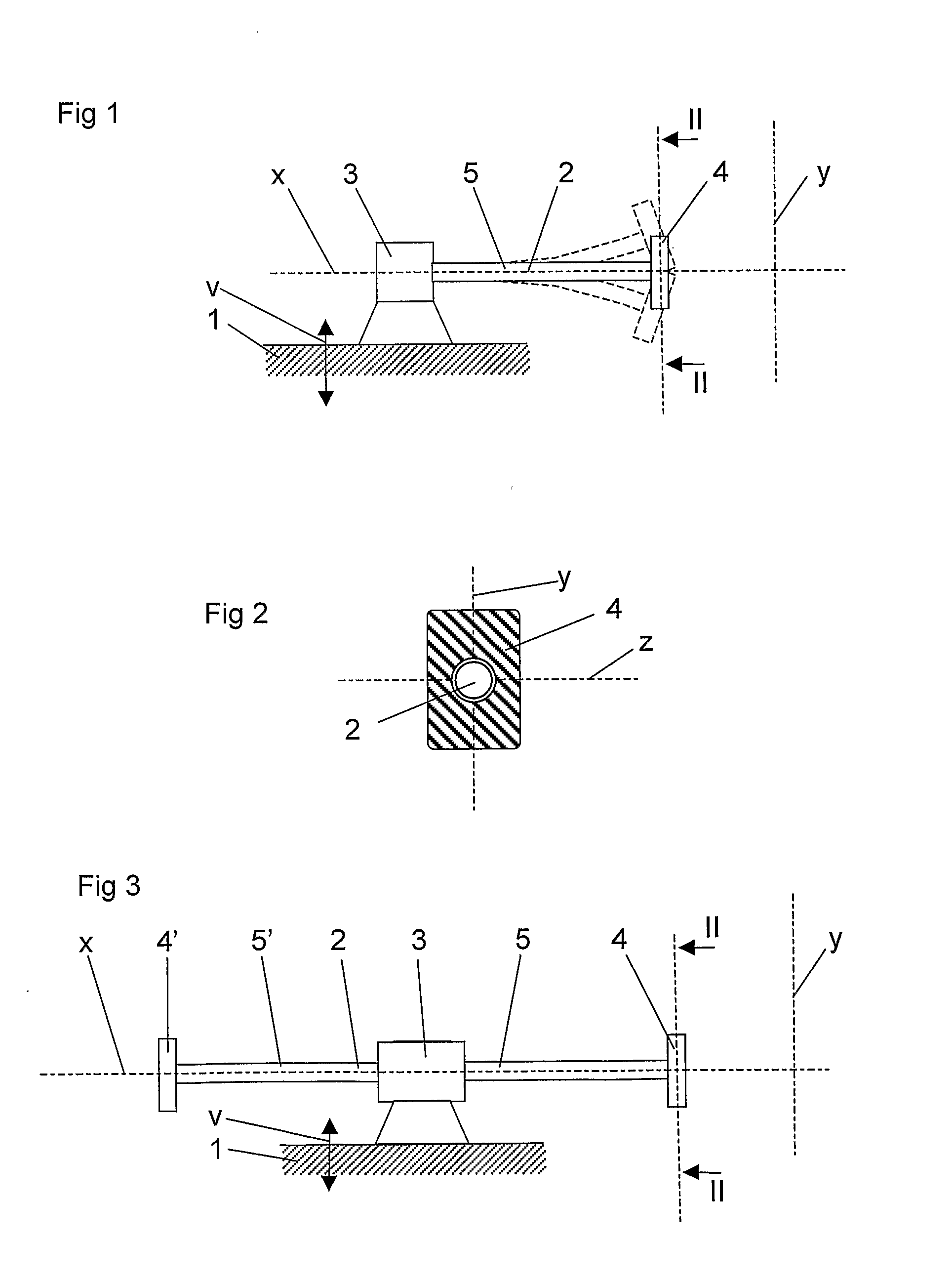
[0022]FIG. 1 discloses a device according to the invention for reducing vibrations and sounds in a structure. This structure may be a vehicle, for instance an aircraft or a ship, or any other stationary structure, for instance a building, a machine tool or any structure where it is desirable to reduce vibrations.

[0023]The device according to the first embodiment comprises a primary connection element 2. The primary connection element 2 is in the first embodiment designed as an elongated rod which extends in a longitudinal direction. The primary connection element 2 is with a part thereof fixedly mounted in relation to the structure 1 via an attachment 3. In the first embodiment, the primary connection element 2 is with an end part fixedly connected to the attachment 3 and the structure 1.

[0024]The device also comprises a dynamic element 4, which has a determined mass-moment of inertia. The dynamic element 4 gives rise to forces of inertia when it is accelerated in a translation move...

fifth embodiment

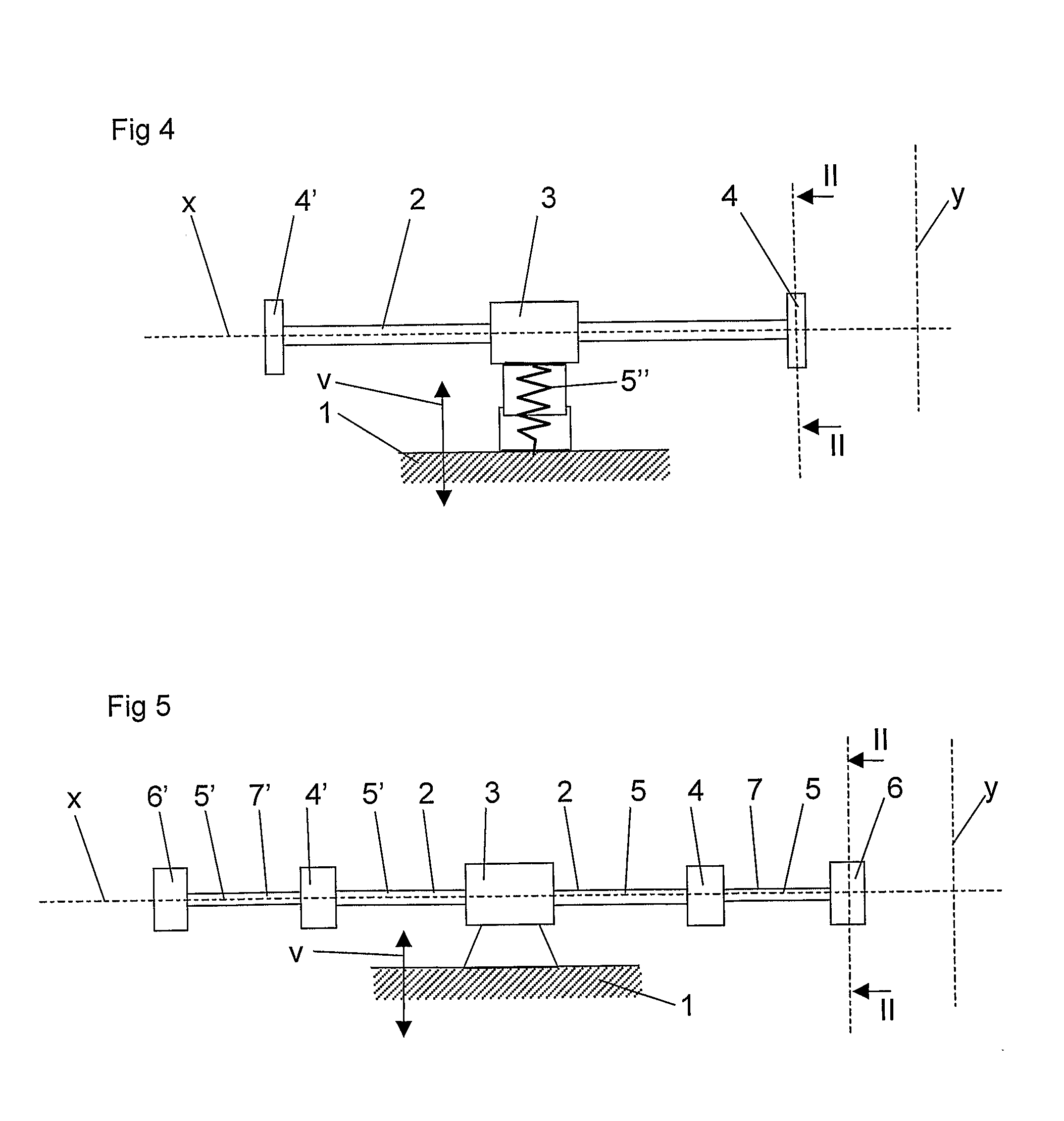
[0032]The spring element 5, 5′ and the dynamic element 4, 4′ of the primary connection element 3 then form a first dynamic unit, whereas the spring element 5, 5′ and the further dynamic elements 6, 6′ of the secondary connection elements 7, 7′ form a second dynamic unit. a device is achieved, which can be adapted to 22, i.e. 4 different frequencies. It is to be noted that in principal it is possible to provide further dynamic elements which are rotatably connected to the outer ends of the secondary connection elements 7, 7′. In such away the number of dynamic units may be further increased, wherein the device can be adapted to 2N different frequencies, where N is the number of dynamic units.

[0033]The device according to the invention will thus by itself provide a rotation of the dynamic elements 4, 4′ around the axis x of rotation to an optimum position for different operation states. This adaptation takes place spontaneously without any particular, forced rotation of the dynamic e...


PUM


Abstract

The invention refers to a device for reducing vibrations and sounds in a structure (1). The device comprises at least a dynamic element (4), which extends along two main axes and has a mass-moment of inertia, and at least a spring element (5) which is connected to the dynamic element (4) and which is adapted to be connected to the structure. The mass-moment of inertia is different with respect to the two main axes. The dynamic element is rotatable around an axis (x) of rotation, which is perpendicular to the two main axes.

Description

CROSS-REFERENCE TO RELATED APPLICATIONS[0001]This application is entitled to the benefit of and incorporates by reference essential subject matter disclosed in International Application No. PCT / SE2006 / 000153 filed on Feb. 2, 2006 and Swedish Patent Application No. 0500245-6 filed on Feb. 2, 2005 and Swedish Patent Application No. 0500491-6 filed Mar. 3, 2005.FIELD OF THE INVENTION[0002]The present invention refers to a device for reducing vibrations and sounds in a structure according to the preamble of claim 1.BACKGROUND OF THE INVENTION[0003]In many various technical applications, such as in aircraft, motor vehicles, ships, various machines and industrial plants, it is desirable to reduce vibrations and sounds. Such vibrations or sounds can have one or several main fundamental frequencies. In aircraft, at least one fixed motor speed, which offers an economically advantageous balance between fuel cost and speed, is frequently utilized. This motor speed results in vibrations and sou...

Claims


Application Information

Patent Timeline
Patent Type & Authority Applications(United States)
IPC IPC(8): F16F7/10
CPCF16F7/104
Inventor GUSTAVSSON, MATS
Owner A2 ACOUSTICS
Why Eureka
Try Eureka