Multipurpose Sucker

a multi-purpose, sucker technology, applied in the direction of machine supports, other domestic objects, mechanical apparatus, etc., can solve the problems of limiting the shape and function of the hanger tool, the functional member loosening, and the difficulty of hooking or hanging heavy objects on the sucker

Inactive Publication Date: 2008-12-18
KIM CHUN DONG
View PDF0 Cites 22 Cited by
  • Summary
  • Abstract
  • Description
  • Claims
  • Application Information

AI Technical Summary

Benefits of technology

[0011]Therefore, the multipurpose sucker in accordance with the present invention has an effect of firmly adhering to an adherend by having a pressure member.
[0012]Also, the multipurpose sucker in accordance with the present invention has various fields of usage without limitation in shape and function of a functional member, by making a pressure member itself rotates to make the center of the suction member available for a functional member of any shape.
[0013]And also, the multipurpose sucker in accordance with the present invention can prevent the suction member from being separated from the adherend in advance by knowing the adhesion strength of the suction member by the cap made from an elastic material.

Problems solved by technology

Also, it is hard to hook or hang heavy objects on the sucker, because of its weak suction force.
However, the conventional sucker has a problem that the assembly of the functional member gets loose to weaken the suction force as the functional member is used over and over again.
This puts a limit on the shape and function of the hanger tool.
Also, the center of the sucker can be lifted with a limit, which results from the limited movement range of the operating lever.
Therefore, the degree of a vacuum formed by operating the operating level is not high enough to support a heavy object, so that the sucker have not been used in the various fields.

Method used


Image

  • Multipurpose Sucker
  • Multipurpose Sucker
  • Multipurpose Sucker

Examples


first embodiment

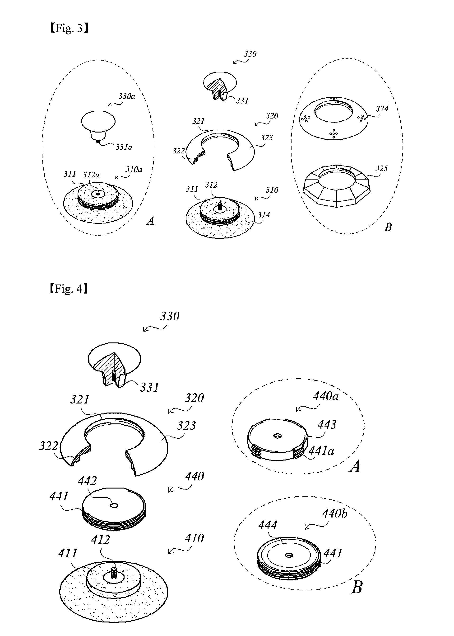
[0037]FIG. 3 is an exploded perspective view showing a multipurpose sucker in accordance with the present invention.

[0038]The multipurpose sucker in accordance with the first embodiment of the present invention is adhered and fixed to an adherend 300 and includes a suction member 310 which is made from soft synthetic resins, a pressure member 320 which secures the adhesion of the suction member 310, and a functional member 330 which is connected with the suction member 310. The functional member can have various shapes and functions.

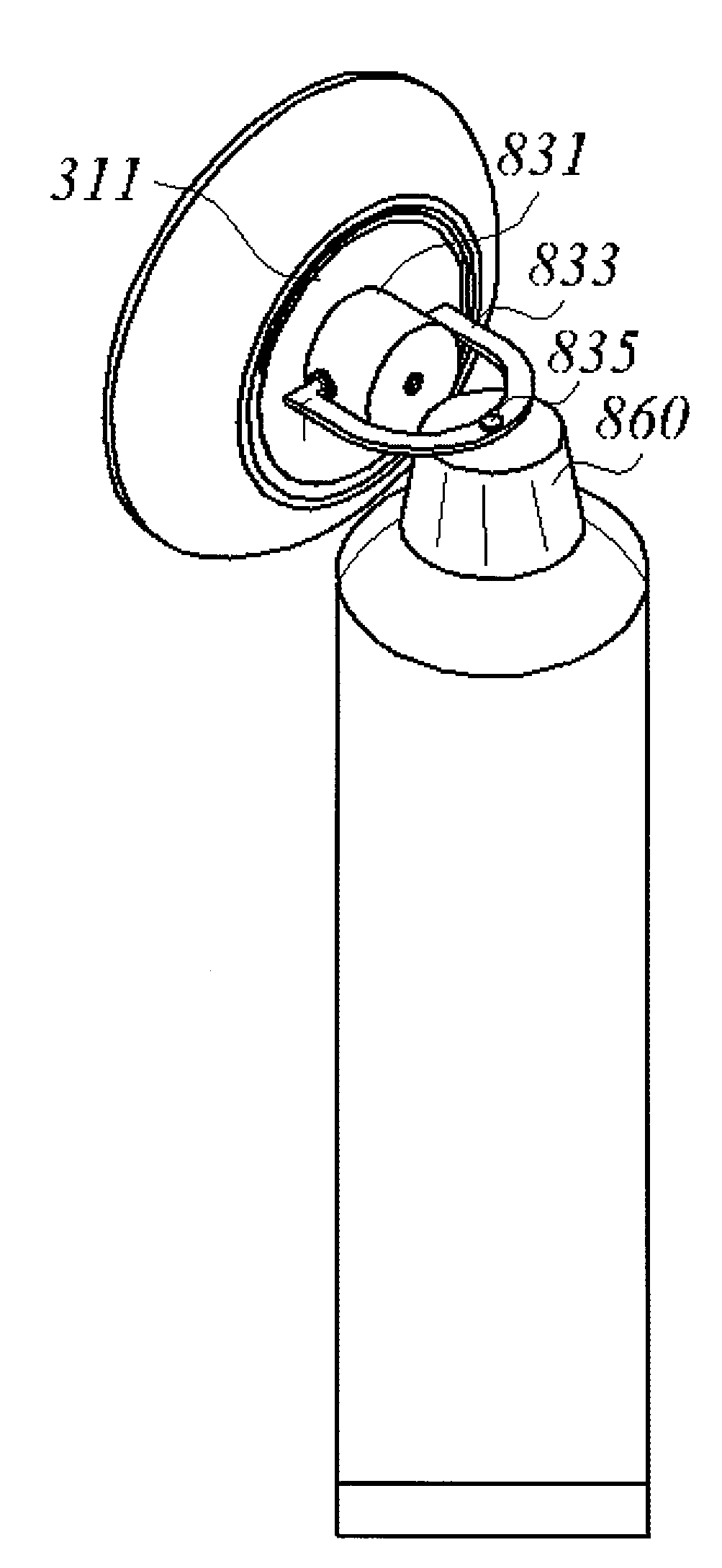
[0039]The suction member 310 includes a connection part 311 in a shape of a disc and a screw member 312 connected to the connection part 311 as one body and located on the center of the connection part 311. The connection part 311 in accordance with the first embodiment of the present invention has a screw groove formed on an external circumference to be jointed with the pressure member 320.

second embodiment

[0040]As shown in FIG. 4, the connection part 411 in accordance with the present invention has a smooth circumference without a screw groove. When the circumference of the connection part 411 is made smooth, a cap 440 to be assembled with the pressure member 320 is equipped. A hole 442 is formed at the center of the cap 440, and screw grooves are formed on the circumference of the cap 440. The cap 440 is combined with the connection part 411 by interference fitting, and is located to be fixed between the functional member 330 and the connection part 411. The cap 440 can be made of material which is stronger than the material of the suction member 410 or the same material as the pressure member 320.

[0041]Also, the cap 440a in accordance with another embodiment of the present invention is made from an elastic material as shown in FIG. 4A, and includes a screw groove part which partially forms screw grooves 441a at the external circumference of the cap 440. The screw groove part 443 is...

third embodiment

[0051]FIG. 10 is a side view showing a multipurpose sucker in accordance with the present invention.

[0052]The multipurpose sucker in accordance with a third embodiment of the present invention is equipped with two sets of the components of the multipurpose sucker other than a functional member, and a functional member 630, with a ‘□’ shape.

[0053]The functional member 630 is assembled with the screw member 312, and then the suction member 310 is adhered to the adherend 300. At this time, pressure member 320 is not assembled with the connection part 311 and located between the functional member 630 and the suction member 310. The suction member 310 is closely adhered to the adherend 300, and then the connection part 311 is assembled with the pressure member 320. The resulting multipurpose sucker can be used for a user's purpose.


PUM


Abstract

The present invention relates to a multipurpose sucker; and, more particularly, to a multipurpose sucker capable of improving a suction force of a suction member by having an additional pressure member. The multipurpose sucker can be stably attached without limitation by a shape of a fundamental member connected to the suction member. The multipurpose sucker includes a suction member for attaching to an adherend, which includes a connection part on a top portion thereof, wherein the connection part forms a screw groove on an external circumference thereof, a screw member equipped with the connection part as one body; a pressure member for pressing the suction member, which includes a connection hole for being assembled with the connection part, wherein the connection hole has a screw groove on an inner wall of the connection hole and a functional member which is assembled with the screw member. Therefore, the multipurpose sucker in accordance with the present invention has an effect of firmly adhering to an adherend by having a pressure member. Also, the multipurpose sucker in accordance with the present invention has various fields of usage without limitation in shape and function of a functional member, by making a pressure member itself rotates to make the center of the suction member available for a functional member of any shape. And also, the multipurpose sucker in accordance with the present invention can prevent the suction member from being separated from the adherend in advance by knowing the adhesion strength of the suction member by the cap made from an elastic material.

Description

TECHNICAL FIELD[0001]The present invention relates to a multipurpose sucker; and, more particularly, to a multipurpose sucker capable of improving a suction force of a suction member by having an additional pressure member. The multipurpose sucker can be stably attached without limitation by a shape of a fundamental member connected to the suction member.BACKGROUND ART[0002]Generally, a sucker is made from rubber material and used for fixing a body to a surface, such as a wall. However, a sucker is easily detached as external air flows into the inside of a suction surface of the sucker little by little as time goes by. Also, it is hard to hook or hang heavy objects on the sucker, because of its weak suction force. According to one prior art, there has been suggested a sucker with an improved suction force in order to solve the problems shown above.[0003]FIG. 1 is a sectional view illustrating a conventional sucker with an improved suction force. The conventional sucker includes a su...

Claims


Application Information

Patent Timeline
Patent Type & Authority Applications(United States)
IPC IPC(8): F16B47/00
CPCA47G29/08B43K23/001B65D51/242F16B45/00F16B47/00F16B47/006
Inventor KIM, CHUN-DONG
Owner KIM CHUN DONG
Why Eureka
Try Eureka