Radiation detection schemes, apparatus and methods of transmitting radiation detection information to a network

a radiation detection and network technology, applied in the field of radiation detection, can solve the problems of unreliable physical symptoms, no way to perform radiation exposure triage,

Inactive Publication Date: 2008-12-18
IBM CORP
View PDF14 Cites 27 Cited by
  • Summary
  • Abstract
  • Description
  • Claims
  • Application Information

AI Technical Summary

Problems solved by technology

In the event of a nuclear event such as a conventional or “dirty” nuclear weapon occurring in a metropolitan, suburban or rural area, there are two problems that would arise immediately for healthcare providers and first responders.
The first problem would be determining the extent of radiation exposure for persons brought to hospitals or being treated by first responders.
In the case where there is a large numbers of potential victims and limited healthcare resources, triage becomes essential, but there is currently no way to perform radiation exposure triage absent physical symptoms, and wherein those physical symptoms can be unreliable.
The second problem is determining both the geographic extent and exposure level distribution of the radiation event as well as determining an estimate of the number of potential victims in the area effected.

Method used


Image

  • Radiation detection schemes, apparatus and methods of transmitting radiation detection information to a network
  • Radiation detection schemes, apparatus and methods of transmitting radiation detection information to a network
  • Radiation detection schemes, apparatus and methods of transmitting radiation detection information to a network

Examples


first embodiment

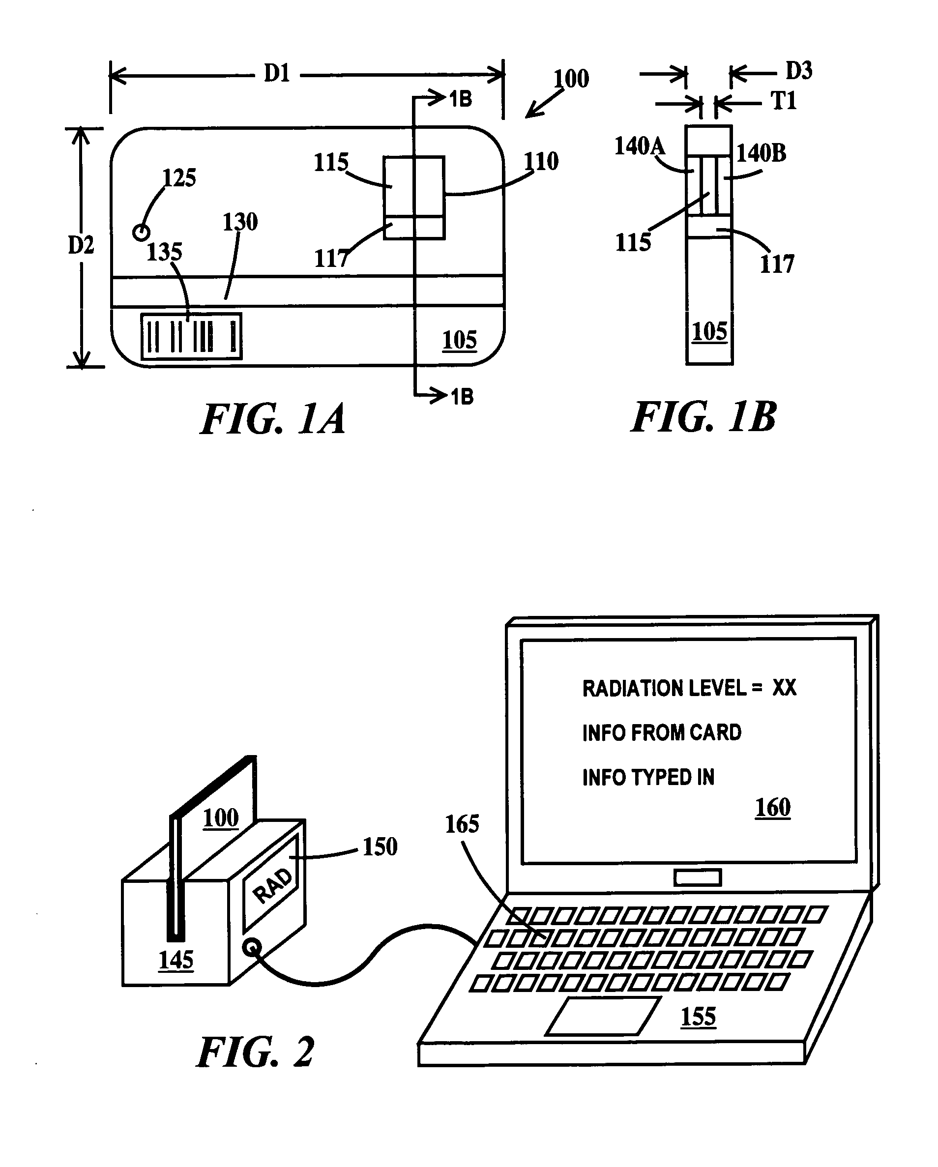
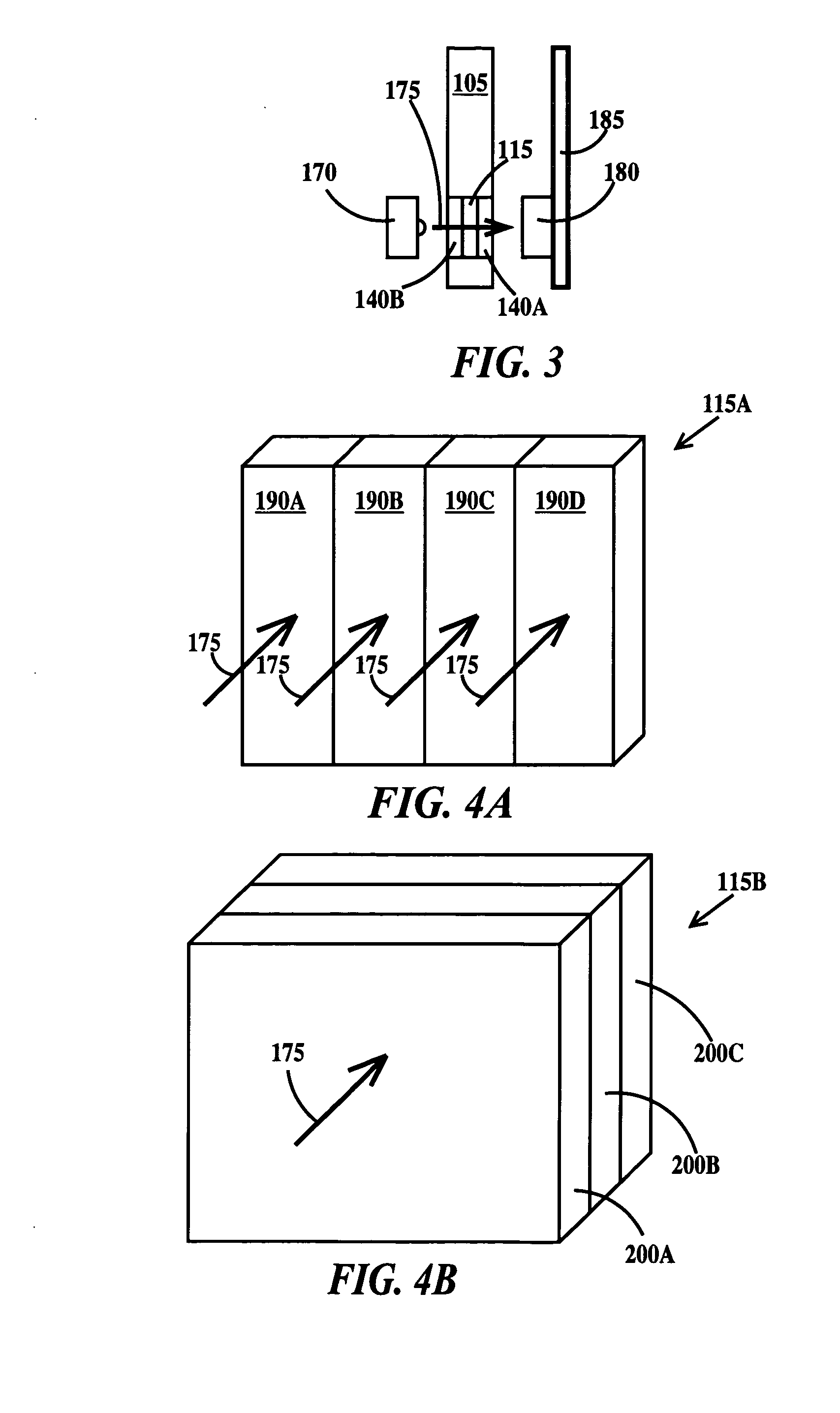
[0027]FIG. 1A is a plan view and FIG. 1B is a cross-section view through line 1B-1B of a passive radiation detection device according to the present invention. In FIG. 1A, a passive radiation device 100 includes a body 105, an opening 110 (or a window 110) in the body and a radiation detection layer 115 within opening 110. Body 105 may be formed from plastic or metal. While primarily intended to be used with a reading device for improved accuracy, and for archiving or recording the exposure, opening 110 may include an optional reference region 117, insensitive to radiation, but having a set of regions varying in optical density, color or color intensity corresponding to a known dose of radiation that may be manually compared (by a person looking through opening 110) to the optical density, color or color intensity of radiation detection layer 115. Alternatively, a comparison can be made between radiation detection layer 115 and reference region 117 located on the side of the detecto...

second embodiment

[0042]FIG. 5 is a schematic diagram of an active radiation detection device according to the present invention. In FIG. 5, a host device includes a first memory array 210 for detecting a radiation exposure event, a second memory array 215 for storing information relating to the radiation exposure event, a third memory 220 which functions as the normal memory of the host device, a microprocessor (CPU) / logic circuit 225 including a radiation exposure event detection / control circuit 230, an optional I / O device (i.e. a cable socket) an optional global positioning unit 240, a transmitter or transceiver 245 and an antenna 250, all electronically coupled together. Alternatively, second memory 215 may be incorporated into radiation exposure event detection / control circuit 230. Positioned over and under first memory array 210 are alpha particle generating plates 255. Positioned over and under second and third memory arrays 215 and 220 respectively are optional radiation blocking shields 260 ...

third embodiment

[0068]FIG. 11 is a schematic diagram of an active radiation detection device according to the present invention. In FIG. 11, a host device 320 is similar to host device 205 of FIG. 5 except for the fact that first memory array 210 and alpha particle generating plates 255 are replaced with a micro-Geiger counter 325.

[0069]FIG. 12A is a plan view and FIG. 12B is a cross-sectional view through line 12B-12B of FIG. 12A of a radiation detection element according to the third embodiments of the present invention. In FIG. 12A, micro-Geiger counter 325 includes, suspended in a cavity 330, a multiplicity of metal wires 335. All first ends of wires 335 are integrally formed with a first bus bar 340 and all second ends of wires 335 are integrally formed with a second bus bar 345. Micro-Geiger counter 325 includes seal 350, whose use is illustrated in FIG. 12B. First bus bar 340 is coupled through a voltage meter to a high voltage source. Second bus bar 345 is electrically floating. In one exam...


PUM


Abstract

Personal radiation detection devices, methods of obtaining radiation exposure data, and networks of personal radiation devices. The detection devices may include passive devices and active devices. The passive detection devices may have the same form factor as credit cards or be included in common types of credit card form factor sized cards. The active devices may be incorporated into common and widely distributed host devices.

Description

FIELD OF THE INVENTION[0001]The present invention relates to the field of radiation detection; more specifically, it relates to radiation detection schemes and apparatus and methods of transmitting radiation detection information to a network.BACKGROUND OF THE INVENTION[0002]In the event of a nuclear event such as a conventional or “dirty” nuclear weapon occurring in a metropolitan, suburban or rural area, there are two problems that would arise immediately for healthcare providers and first responders. The first problem would be determining the extent of radiation exposure for persons brought to hospitals or being treated by first responders. In the case where there is a large numbers of potential victims and limited healthcare resources, triage becomes essential, but there is currently no way to perform radiation exposure triage absent physical symptoms, and wherein those physical symptoms can be unreliable. The second problem is determining both the geographic extent and exposure...

Claims


Application Information

Patent Timeline
Patent Type & Authority Applications(United States)
IPC IPC(8): G01T3/00
CPCG01T1/04
Inventor GORDON, MICHAEL S.RODBELL, KENNETH P.WISNIEFF, ROBERT L.
Owner IBM CORP
Why Eureka
Try Eureka