
Automatic document feeder, image reading system including same, and image forming apparatus including same

a document feeder and image reading technology, applied in the direction of electrographic process equipment, thin material processing, instruments, etc., can solve the problems of increasing the load on the motor driver, increasing the value of the current supplied to the motor, increasing the amount of heat generated by the motor, etc., to reduce the cost, reduce the effect of noise, and reduce the size of the machin

Active Publication Date: 2008-12-18
RICOH KK
View PDF8 Cites 19 Cited by
  • Summary
  • Abstract
  • Description
  • Claims
  • Application Information

AI Technical Summary

Benefits of technology

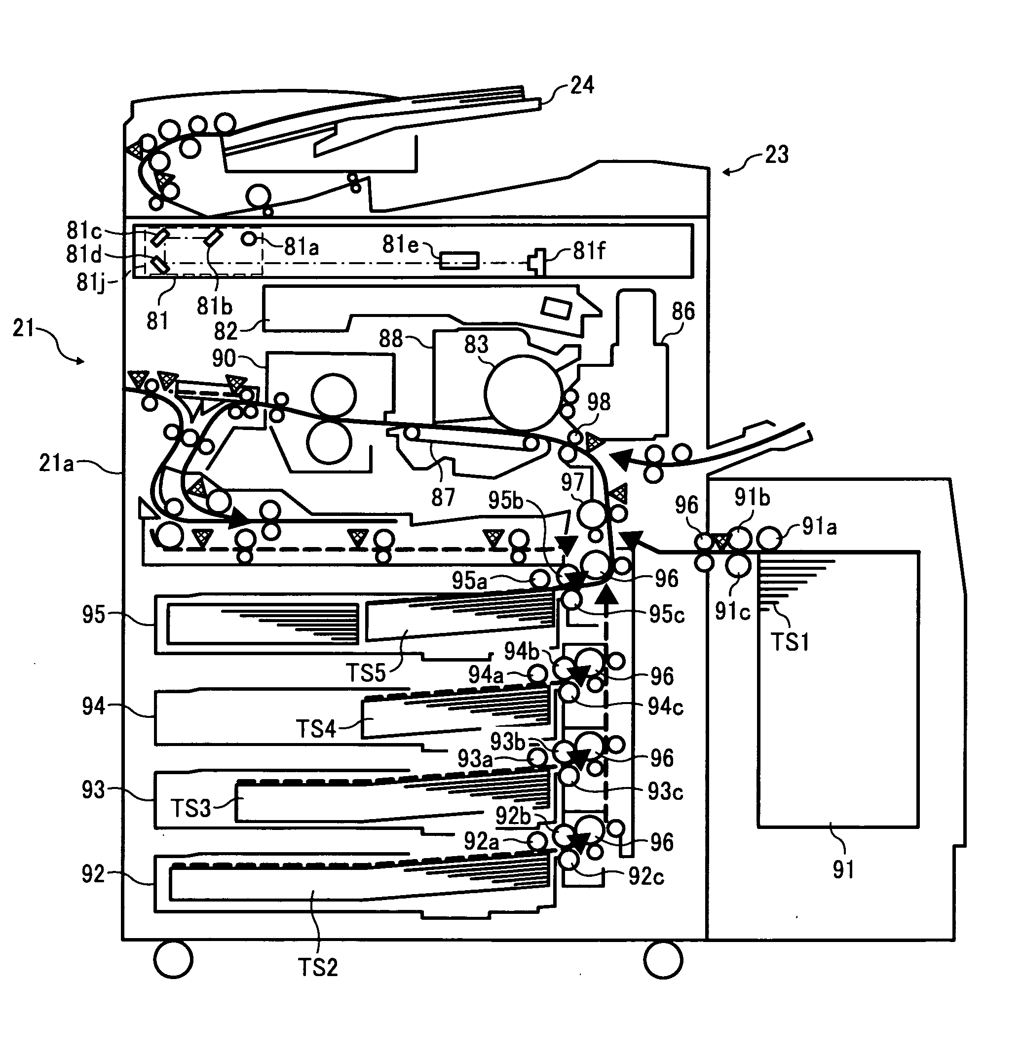
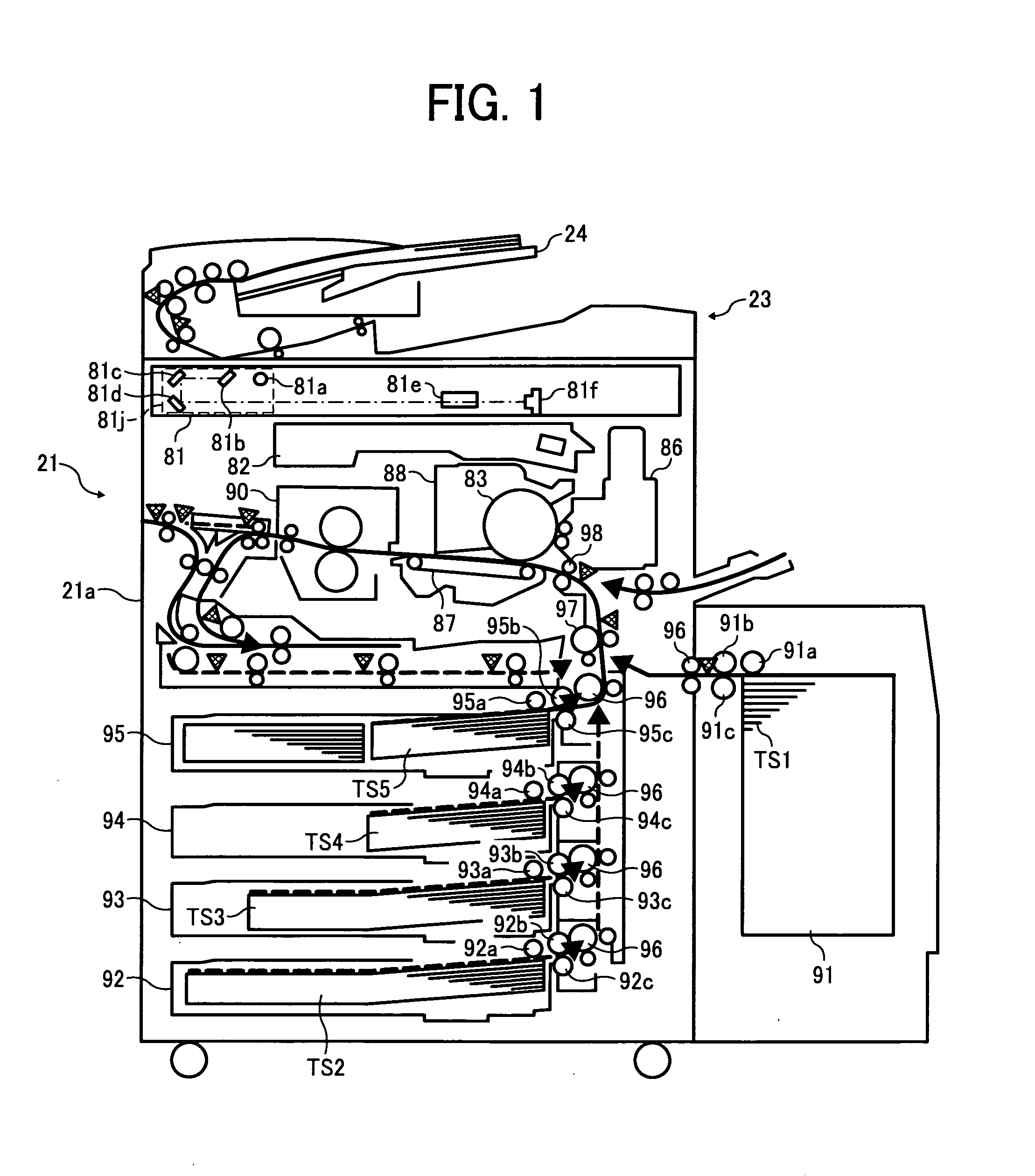
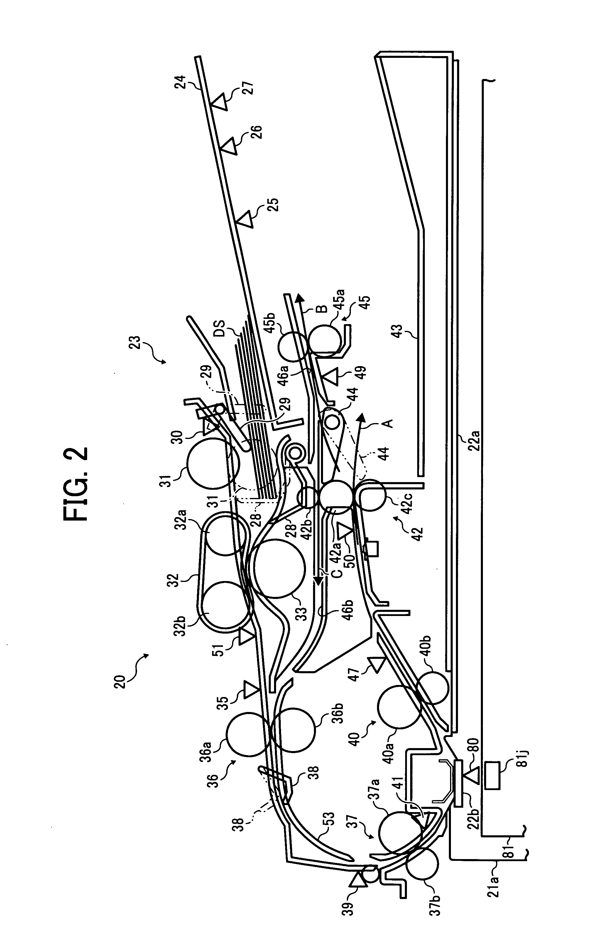
The present patent application proposes an automatic document feeder (ADF) that is small and cost-effective, and can reduce machine size, costs, power consumption, noise, and improve cooling effect. The ADF includes a document separation and feed unit, a document conveyance unit, a document discharging unit, and a cooling member. The cooling member includes a fan motor to supply coolant to the motors. The ADF may be connected to an image reader or an image forming apparatus. The technical effects of the invention include reducing machine size, costs, power consumption, noise, and improving cooling effect.

Problems solved by technology

This generally causes an increase in the value of the current supplied to the motor and a consequent increase in the amount of heat generated by the motor, necessitating appropriate temperature-control countermeasures.
Particularly where a stepping motor is used, such increases in current cause an increase in load on the motor driver, again requiring appropriate temperature control.
However, market demand for downsizing and weight saving of the ADF has led to a reduction of space for cooling and have increased the use of plastic parts that have low thermal conductivity, which hinders effective cooling of the motors, etc.

Method used


Image

  • Automatic document feeder, image reading system including same, and image forming apparatus including same
  • Automatic document feeder, image reading system including same, and image forming apparatus including same
  • Automatic document feeder, image reading system including same, and image forming apparatus including same

Examples


Embodiment Construction

[0064]It will be understood that if an element or layer is referred to as being “on”, “against”, “connected to” or “coupled to” another element or layer, then it can be directly on, against, connected or coupled to the other element or layer, or intervening elements or layers may be present. In contrast, if an element is referred to as being “directly on”, “directly connected to” or “directly coupled to” another element or layer, then there are no intervening elements or layers present. Like numbers referred to like elements throughout. As used herein, the term “and / or” includes any and all combinations of one or more of the associated listed items.

[0065]Spatially relative terms, such as “beneath”, “below”, “lower”, “above”, “upper” and the like may be used herein for ease of description to describe one element or feature's relationship to another element(s) or feature(s) as illustrated in the figures. It will be understood that the spatially relative terms are intended to encompass...


PUM


Abstract

An automatic document feeder, included in an image reading system that can be included in an image forming apparatus, is configured to transfer an original document to an image reader included in the image reading system, and includes a first drive unit configured to include a first motor to drive the document separation and feed unit, a second drive unit configured to include a second motor to drive the document conveyance unit, a third drive unit configured to include a third motor to drive the document discharging unit, where at least two motors of the first, second, and third motors disposed in a substantially in-line arrangement, and a cooling member configured to supply a coolant to the at least two motors disposed in a substantially in-line arrangement, to the first, second, and third motors, in that order.

Description

CROSS-REFERENCE TO RELATED APPLICATION[0001]The present patent application claims priority under 35 U.S.C. §119 from Japanese Patent Application No. 2007-157650 filed on Jun. 14, 2007 in the Japan Patent Office, the contents and disclosure of which are hereby incorporated by reference herein in their entirety.BACKGROUND[0002]1. Field[0003]Example embodiments of the present patent application generally relate to an automatic document feeder, an image reading system including the automatic document feeder, and an image forming apparatus including the automatic document feeder or including the image reading system with the automatic document feeder. More particularly, the present patent application relates to an automatic document feeder that conveys an original document, an image reading system that includes the automatic document feeder and reads the original document a scanning position, and an image forming apparatus that includes the image reading system having the automatic docum...

Claims


Application Information

Patent Timeline
Patent Type & Authority Applications(United States)
IPC IPC(8): B65H5/00
CPCG03G15/602G03G2215/00189
Inventor TOBINAGA, HIDEKINAGANO, TATSUAKIKOSUGA, YASUOKIMURA, NORIOAKAI, TAKESHI
Owner RICOH KK
Learn More