Slide Vane for Hydraulic Power Steering

Active Publication Date: 2008-12-18
KNORR-BREMSE SYST FUER NUTZFAHRZEUGE GMBH
View PDF11 Cites 0 Cited by
  • Summary
  • Abstract
  • Description
  • Claims
  • Application Information

AI Technical Summary

Benefits of technology

[0008]It is the object of the present invention to provide a slide vane that remedies the disadvantages associated with the prior art. In particular, said slide vane should reduce the manufacturing costs associated with known slide vanes and allow for additional functionalities as compared to the known rotary slide vanes. For example, the rotary slide vane will permit the application of a steering torque by means of an auxiliary motor.
[0011]Accordingly, there is provided, in accordance with the invention, control grooves disposed in the circumferential direction of the control sleeve and sliding sleeve, or the input shaft and output shaft, as opposed to the longitudinal direction of the subject sleeves and shafts. The circumferential disposition of the control grooves with respect to the control sleeve and sliding sleeve, or the input shaft and output shaft offers the major advantage that all of the control grooves may be manufactured using a low-cost turning process.

Problems solved by technology

For this reason, manufacturing of the control edges requires complex and cost-intensive manufacturing methods.
It is precisely the manufacturing of the control grooves running in the axial direction, in particular also described in the printed documents mentioned, that involves considerable expense.
In particular the longitudinal grooves of the control sleeve, which lie inside, place increased demands on the manufacturing process.
Another disadvantage of known rotary slide vanes is that they do not allow for implementing certain functionalities comprising electrically assisted power steering using hydraulically assisted power steering.
Applying a steering torque is hardly possible or only at considerable expense using a hydraulically assisted system having the described rotary slide vanes.

Method used


Image

  • Slide Vane for Hydraulic Power Steering
  • Slide Vane for Hydraulic Power Steering
  • Slide Vane for Hydraulic Power Steering

Examples


Embodiment Construction

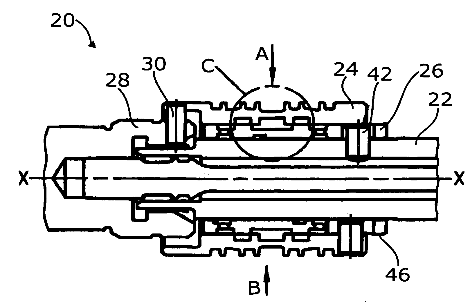
[0022]FIG. 1 shows a slide vane 20 of the invention that comprises a sliding sleeve 26 positioned between an input shaft 22 and a control sleeve 24. Said control sleeve 24 and the sliding sleeve 26 are of a tubular configuration, the sliding sleeve 26 being located substantially within the control sleeve 24. The input shaft 22 is connected to a steering wheel via a longitudinal column (not illustrated), whereas the control sleeve 24 is non-rotatably fastened to an output shaft 28. Said output shaft 28 is in turn indirectly connected to wheels that are to be rotated.

[0023]In the exemplary embodiment shown, the control sleeve 24 is fastened to the output shaft 28 via a pin 30.

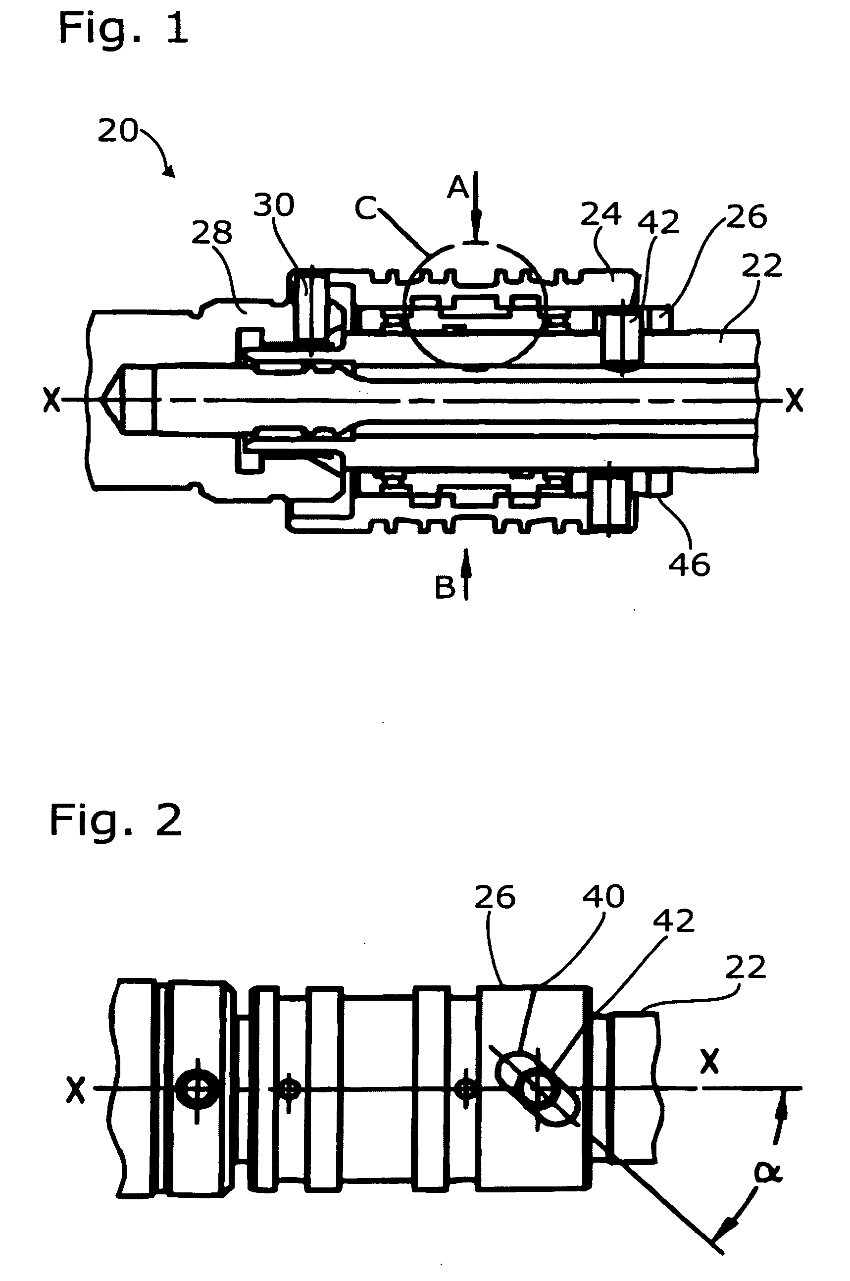
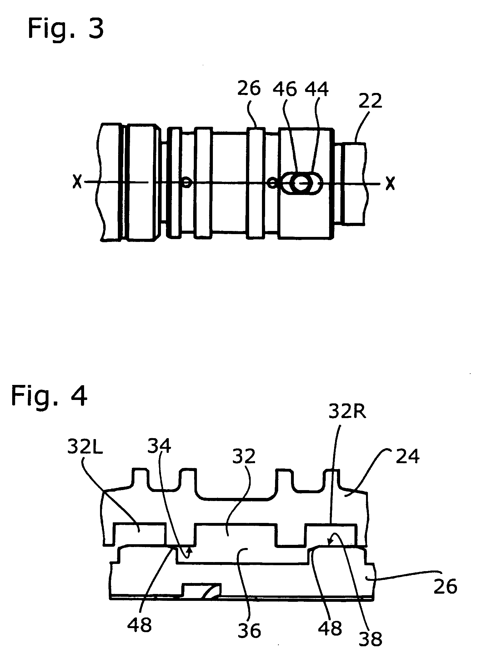
[0024]The sliding sleeve 26 is movable in an axial direction along a longitudinal axis x-x of the slide vane 20. As a result, displacement or movement of the sliding sleeve may position the second control grooves 36, which are defined by an outer surface 38 of the sliding sleeve 26, to coincide or cooperate with ...


PUM


Abstract

The invention relates to a slide vane (20) for a hydraulic power steering of automotive vehicles with a tubular control sleeve (24). Said control sleeve is connected to an output shaft (28) and comprises first control grooves (32) in its inner surface (34). Further, there is provided a tubular sliding sleeve (26) that is disposed at least in portions within said control sleeve (24). On its outer surface (38), the sliding sleeve (26) comprises second control grooves (36) that may be brought to coincide with the first control grooves (32) of the control sleeve (24), said first control grooves (32) being disposed substantially in the circumferential direction of the tubular control sleeve (24) and said second control grooves (36) substantially in the circumferential direction of said tubular sliding sleeve (26). The relative position of said control sleeve (24) and of said sliding sleeve (26) being relatively variable in the axial direction

Description

CROSS-REFERENCE TO PRIORITY APPLICATION[0001]This application hereby claims the benefit of the commonly assigned German Patent No. 10 2007 028 529.0 (filed Jun. 18, 2007), which is hereby incorporated by reference in its entirety.FIELD OF THE INVENTION[0002]The present invention relates to a slide vane for a hydraulic power steering of an automotive vehicle, with a tubular control sleeve that is connected to an output shaft and comprises first control grooves in its inner surface.BACKGROUND[0003]Slide vanes, more specifically rotary slide vanes, are known and utilized by default in hydraulic power steering. These slide vanes control the hydraulic pressure and, as a result thereof, the steering assistance on an assistance cylinder as a function of the steering torque applied by the driver. In most cases, rotary slide vanes are utilized wherein an input shaft connected to a steering wheel via a steering column rotates relative to a control sleeve that is connected to the output shaft ...

Claims


Application Information

Patent Timeline
IPC IPC(8): F16L21/00
CPCB62D5/087Y10T137/8667Y10T137/8671
Inventor GROLL, STEPHANKOGAN, ALEXANDER
Owner KNORR-BREMSE SYST FUER NUTZFAHRZEUGE GMBH
Why Eureka
Try Eureka