Position Detector and Method for Detecting a Position of a Packaging Material with Magnetic Marking

a technology of positioning detector and positioning position, which is applied in the direction of magnetic field controlled resistor, sensing record carrier, geological measurement, etc., can solve the problem of frequent difficulties

Inactive Publication Date: 2008-12-18
TETRA LAVAL HLDG & FINANCE SA
View PDF6 Cites 41 Cited by
  • Summary
  • Abstract
  • Description
  • Claims
  • Application Information

AI Technical Summary

Benefits of technology

[0003]In view of the above, an objective of the invention is to solve or at least reduce the problems discussed above. In particular, an objective is to provide a robust position determination of a packaging material.
[0006]An advantage of this is a robust position determination in sense of magnetic interferences from e.g. electric machines and in sense of dust, e.g. from the packaging material. Further, an advantage is that the sensors do not need to be in direct contact with the packaging material. Further, an advantage is simple signal processing.
[0011]These features provides for accurate finding of the zero crossing by either observing the level, or the slope of the signal, or both. These features also enable a fast detection, i.e. no or little latency in providing a detection output signal.

Problems solved by technology

If a magnetic sensor of known type is used for the detection of magnetic markings which have been applied to e.g. a packaging material web in order to control the forwards feed of the web or control some other working operation, difficulties frequently occur owing to the presence of strong magnetic interference fields.

Method used


Image

  • Position Detector and Method for Detecting a Position of a Packaging Material with Magnetic Marking
  • Position Detector and Method for Detecting a Position of a Packaging Material with Magnetic Marking
  • Position Detector and Method for Detecting a Position of a Packaging Material with Magnetic Marking

Examples


Embodiment Construction

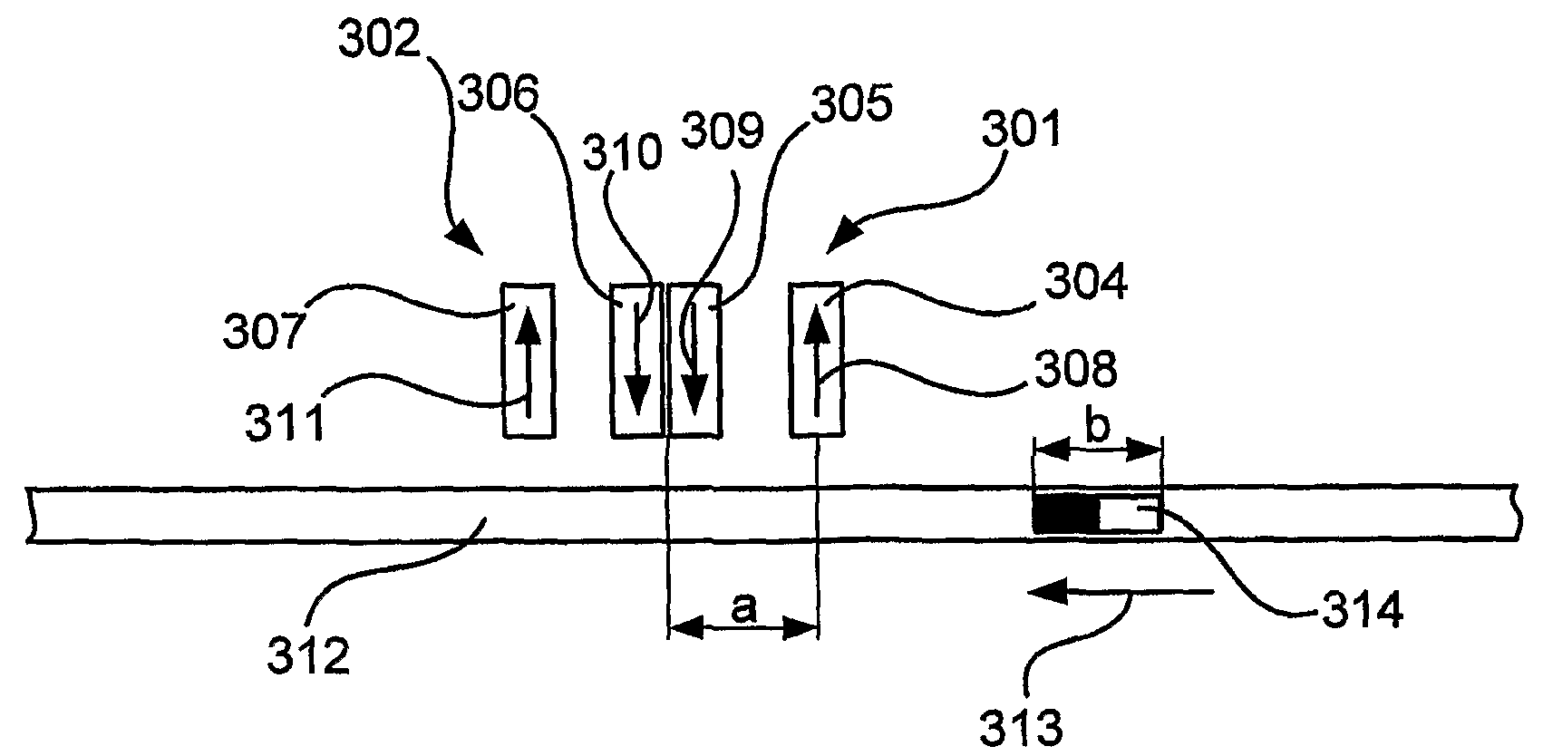
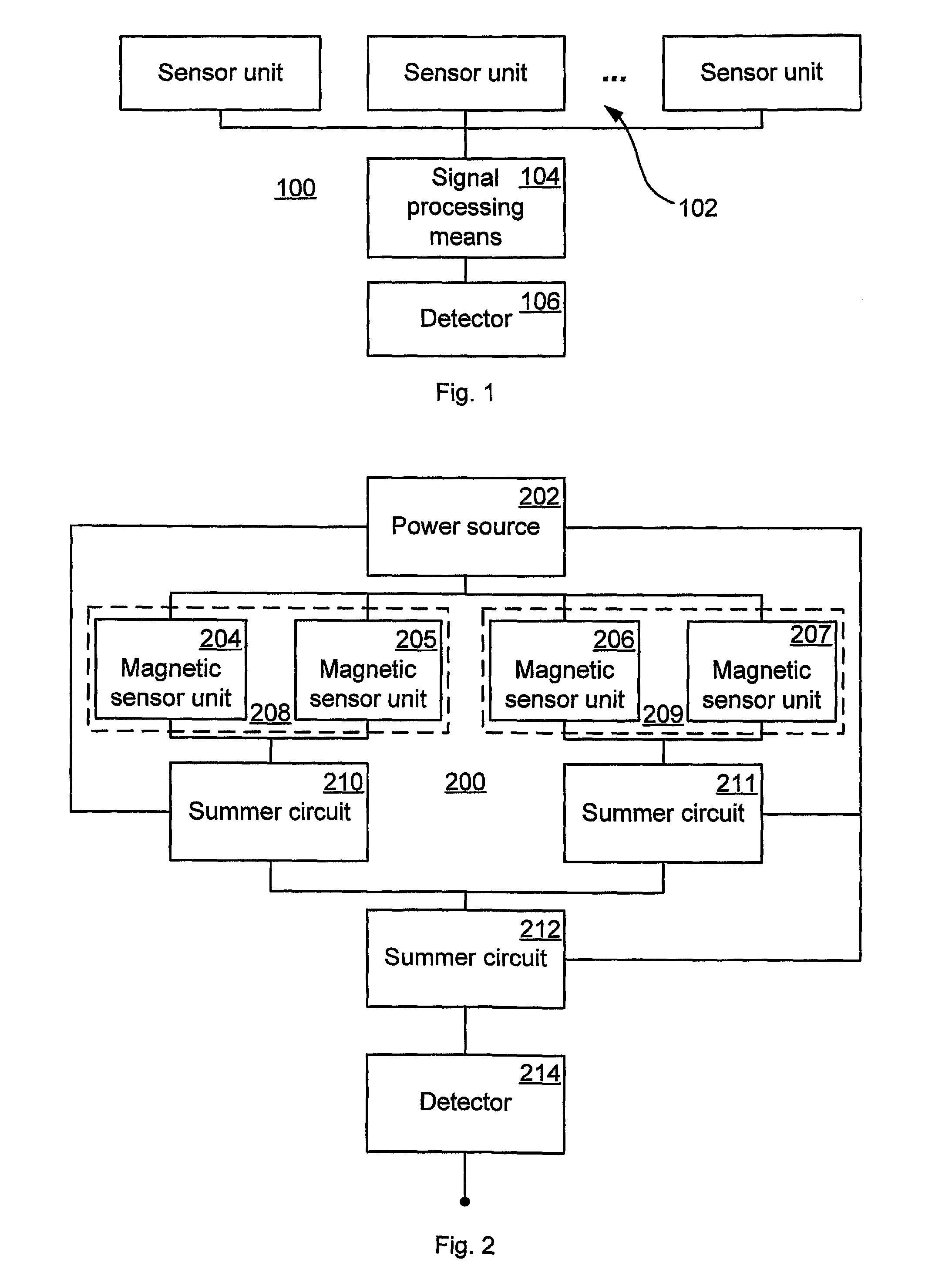
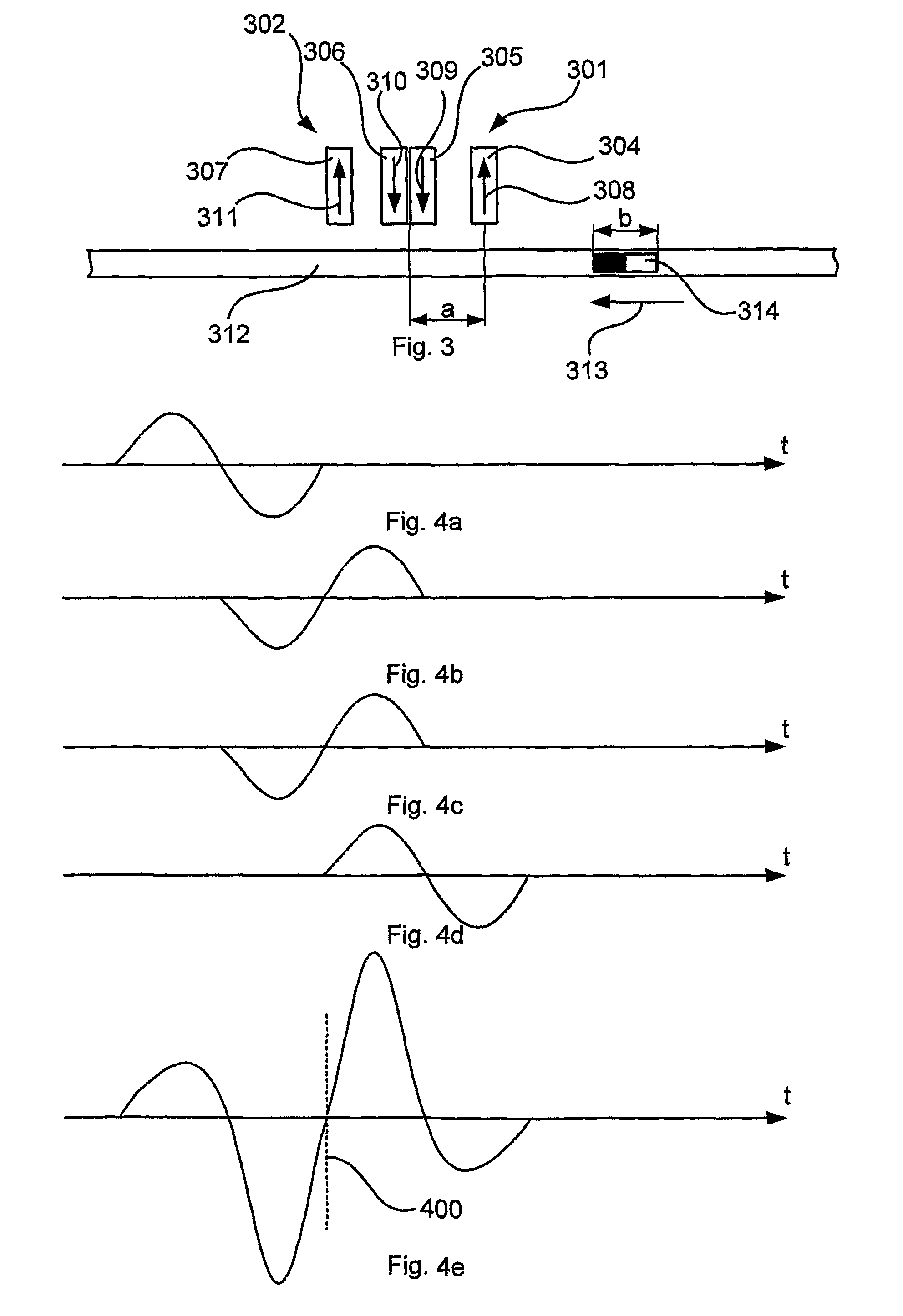
[0041]FIG. 1 is a block diagram schematically showing a position determination apparatus 100 arranged to determine position of a packaging material (not shown) by determining the time when a magnetic marking arranged in, at, or by the material. The apparatus 100 comprises a plurality of sensors 102, which provides output signals responsive to the magnetism of the magnet or magnetic material. The Output signals are aggregated in a signal processing means 104 to produce an aggregated signal, which is provided to a detector 106. The detector 106 determines a position of the magnetic marking from the aggregated signal.

[0042]FIG. 2 is a block diagram schematically showing a position determination apparatus 200 arranged to determine position of a packaging material (not shown) by determining the time when a magnet arranged in, at, or by the material, or a magnetized part of the material passes the apparatus 200. The position determination apparatus 200 comprises a power source 202 for pro...


PUM


Abstract

A position detector arrangement for detecting a position of a packaging material with magnetic marking comprises a sensor assembly comprising a plurality of magnetic sensor units each comprising an output providing an output signal. The magnetic sensor units are arranged in at least two sensor unit pairs, with the sensor units of each pair arranged with opposite sensitivity directions, and with the sensor units arranged to sense magnetic markings of the packaging material. A signal processing assembly is connected to the outputs of the magnetic sensors and comprises a combiner arranged to aggregate the output signals of the sensors to an aggregated signal; and a detector arranged to determine the position of the packaging material from the aggregated signal. Further, a method for detecting a position of a packaging material with magnetic markings is disclosed.

Description

TECHNICAL FIELD[0001]The present invention relates to a position detector arrangement for determining a position of a packaging material with magnetic marking, and a method for determining a position of a packaging material with magnetic marking.BACKGROUND OF THE INVENTION[0002]It is known that magnetic sensors or detector elements can be used for establishing and recording the occurrence of magnetic fields and it is also known that magnetic markings can be arranged on a carrier which are readable by magnetic sensors. If a magnetic sensor of known type is used for the detection of magnetic markings which have been applied to e.g. a packaging material web in order to control the forwards feed of the web or control some other working operation, difficulties frequently occur owing to the presence of strong magnetic interference fields. In a packaging machine, for example, sealings are carried out frequently with the help of induction coils which are supplied with heavy currents and whi...

Claims


Application Information

Patent Timeline
Patent Type & Authority Applications(United States)
IPC IPC(8): G01B7/00
CPCG01B7/003G01R33/025G01D5/145G06K7/084G01V3/081G06K7/087
Inventor HOLMSTROM, GERT
Owner TETRA LAVAL HLDG & FINANCE SA
Why Eureka
Try Eureka