MRI apparatus and RF transmit gain setting method

a technology of transmit gain and magnetic resonance imaging, which is applied in the direction of magnetic measurement, instruments, measurement devices, etc., can solve the problems of increased patient load and inconvenience for users, and achieve the effect of improving calibration efficiency and improving calibration efficiency

Inactive Publication Date: 2008-12-18
GE MEDICAL SYST GLOBAL TECH CO LLC
View PDF17 Cites 1 Cited by
  • Summary
  • Abstract
  • Description
  • Claims
  • Application Information

AI Technical Summary

Benefits of technology

[0026]Since the MRI apparatus according to the invention is an MRI apparatus which obtains a tomogram of an object by utilizing magnetic resonance, including a calibrating device which figures out the relationship between the center frequency and the optimal gain of RF transmission with respect to a predetermined range of central frequencies, a saving device which saves information expressing the relationship, and a setting device which sets the RF transmission gain according to the center frequency during subsequent scanning by utilizing the saved information, an MRI apparatus improving the efficiency of calibration can be realized.
[0027]Further, since the RF transmission gain setting method according to the invention is an RF transmission gain setting method for an MRI apparatus which take a tomogram of an object by utilizing magnetic resonance, wherein the relationship between the center frequency and the optimal gain of RF transmission is figured out in a predetermined range of central frequencies by calibration, information expressing the relationship is saved, and the RF transmission gain is set according to the center frequency during subsequent scanning by utilizing the saved information, an RF transmission gain setting method improving the efficiency of calibration can be realized.

Problems solved by technology

This extends the time required for imaging, with a correspondingly increased load on the patient and inconvenience to the user.

Method used


Image

  • MRI apparatus and RF transmit gain setting method
  • MRI apparatus and RF transmit gain setting method
  • MRI apparatus and RF transmit gain setting method

Examples


Embodiment Construction

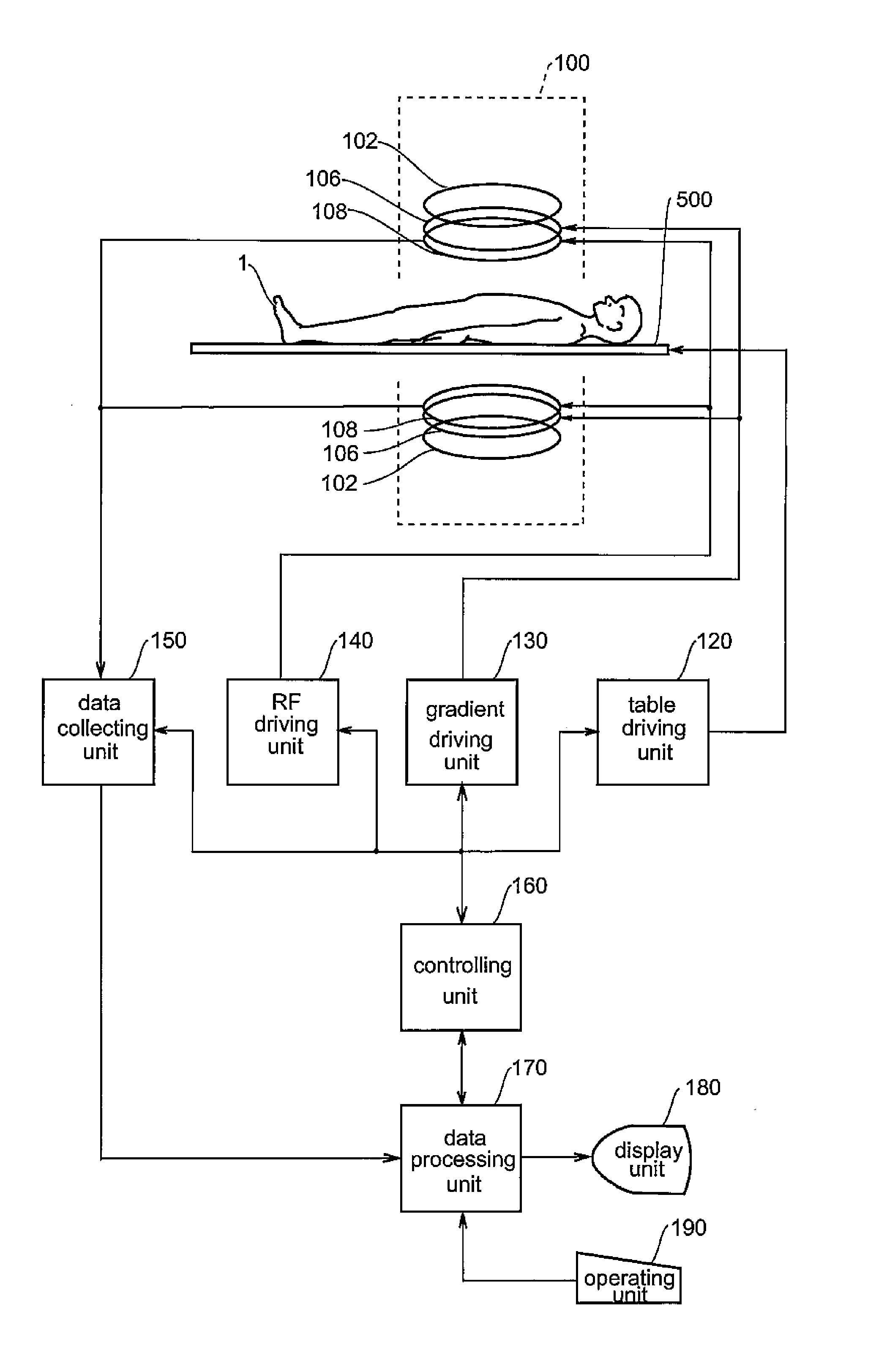
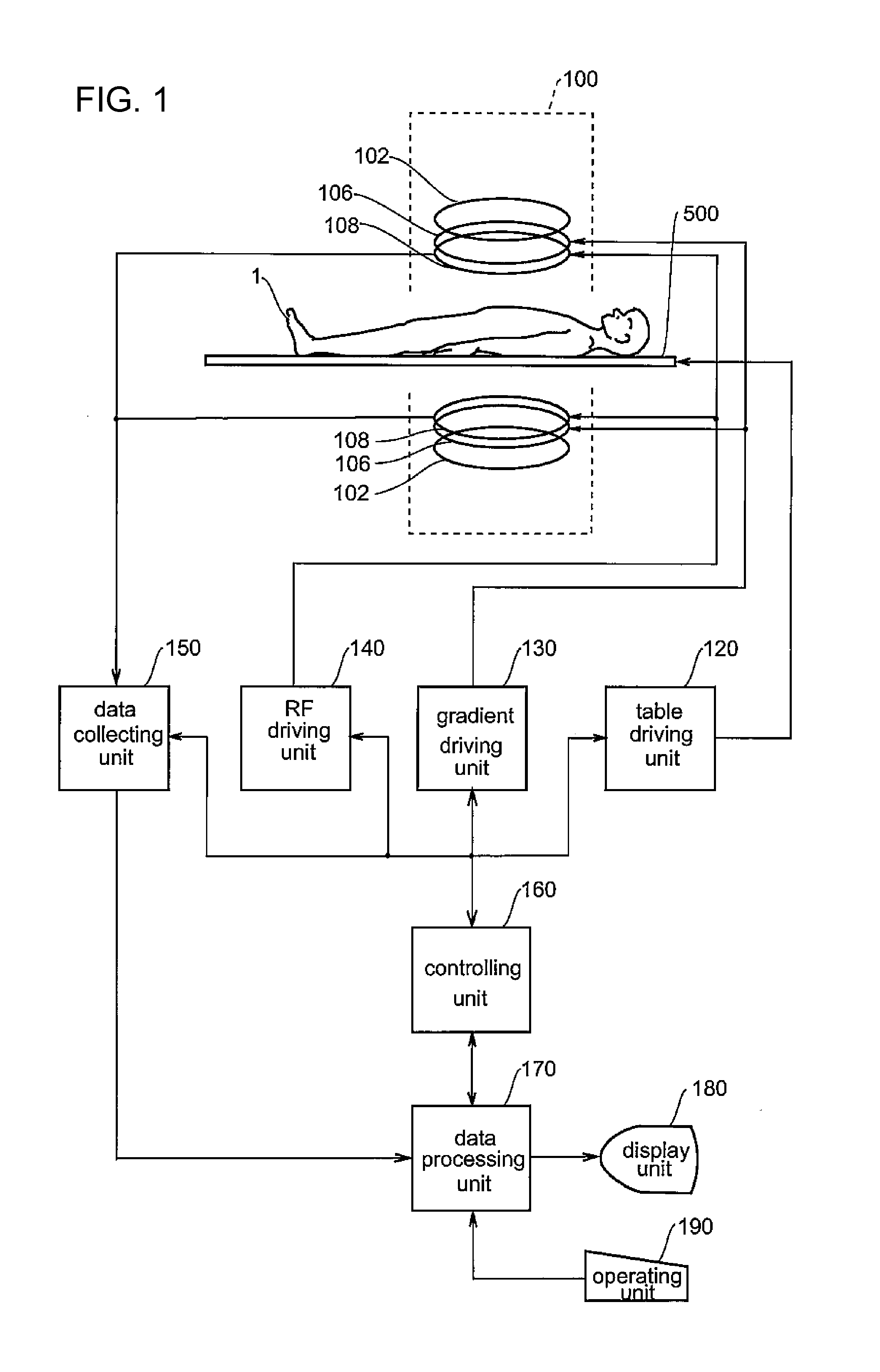
[0043]Best modes for carrying out the invention will be described in detail below with reference to the drawings. Incidentally, the invention is not limited to these best modes for implementing it. A block diagram of an MRI apparatus is shown in FIG. 1. The configuration of this apparatus represents one example of best modes for carrying out the invention regarding MRI apparatuses.

[0044]As shown in FIG. 1, this apparatus has a magnetic field generating device 100. The magnetic field generating device 100 has main magnetic field magnet units 102, gradient coil units 106 and RF coil units 108. An object 1, mounted on a table 500, is brought in and out of the internal space of the magnetic field generating device 100. The table 500 is driven by a table driving unit 120.

[0045]Each item of these main magnetic field magnet units 102, gradient coil units 106 and RF coil units 108 is provided in a pair, one piece opposed to the other with a space in-between. Each has a substantially planar ...


PUM


Abstract

An MRI apparatus which obtains a tomogram of an object by utilizing magnetic resonance includes a calibrating device which figures out a relationship between a center frequency and an optimal gain of RF transmission with respect to a predetermined range of central frequencies, a saving device which saves information expressing said relationship, and a setting device which sets the RF transmission gain according to the center frequency during subsequent scanning by utilizing the saved information.

Description

CROSS REFERENCE TO RELATED APPLICATIONS[0001]This application claims the benefit of Chinese Patent Application No. 200710110317.5 filed Jun. 15, 2007, which is hereby incorporated by reference in its entirety.BACKGROUND OF THE INVENTION[0002]The subject matter disclosed herein relates to an MRI apparatus (Magnetic Resonance Imaging) apparatus and an RF (radio frequency) transmission gain setting method, and more particularly to an MRI apparatus which obtains tomograms of the object by utilizing magnetic resonance and an RF transmission gain setting method for MRI apparatuses.[0003]In an MRI apparatus, a prescan is done before taking an image, and calibration is performed to optimize the central frequency and the gain of RF transmission by using the imaged data. By the calibration, the center frequency of RF transmission is so adjusted as to be identical with the Larmor frequency of the spin of the object, and the gain of RF transmission is so adjusted as to set the flip angle of spi...

Claims


Application Information

Patent Timeline
Patent Type & Authority Applications(United States)
IPC IPC(8): G01R33/58
CPCG01R33/3806G01R33/383G01R33/543G01R33/583
Inventor CAO, KAIDAI, QINGYU
Owner GE MEDICAL SYST GLOBAL TECH CO LLC
Why Eureka
Try Eureka