Input device and method of manufacturing module unit for input device

a technology of input device and manufacturing module, which is applied in the direction of contact mechanism, emergency connection, instruments, etc., can solve the problems of reducing the accuracy of detecting the location of coordinates and becoming more difficult to assemble switches, and achieve uniform height

Inactive Publication Date: 2008-12-18
PANASONIC CORP
View PDF20 Cites 24 Cited by
  • Summary
  • Abstract
  • Description
  • Claims
  • Application Information

AI Technical Summary

Benefits of technology

[0020]According to this method, it becomes possible to manufacture with few assembling processes the module unit for the input device provided with the cushioning member having both the upper and lower surfaces bonded to their corresponding ones of the capacitive sensor and the movable contact assembly while maintaining the uniform height throughout.

Problems solved by technology

This gives rise to a problem of reducing an accuracy of detecting the location of coordinates since it is determined based on the change in the capacitance.
It is therefore becoming more difficult to assemble switches 105 since the operable areas for yielding an excellent tactile feeling to the push-on operation become smaller with this trend of downsizing.

Method used


Image

  • Input device and method of manufacturing module unit for input device
  • Input device and method of manufacturing module unit for input device
  • Input device and method of manufacturing module unit for input device

Examples


first exemplary embodiment

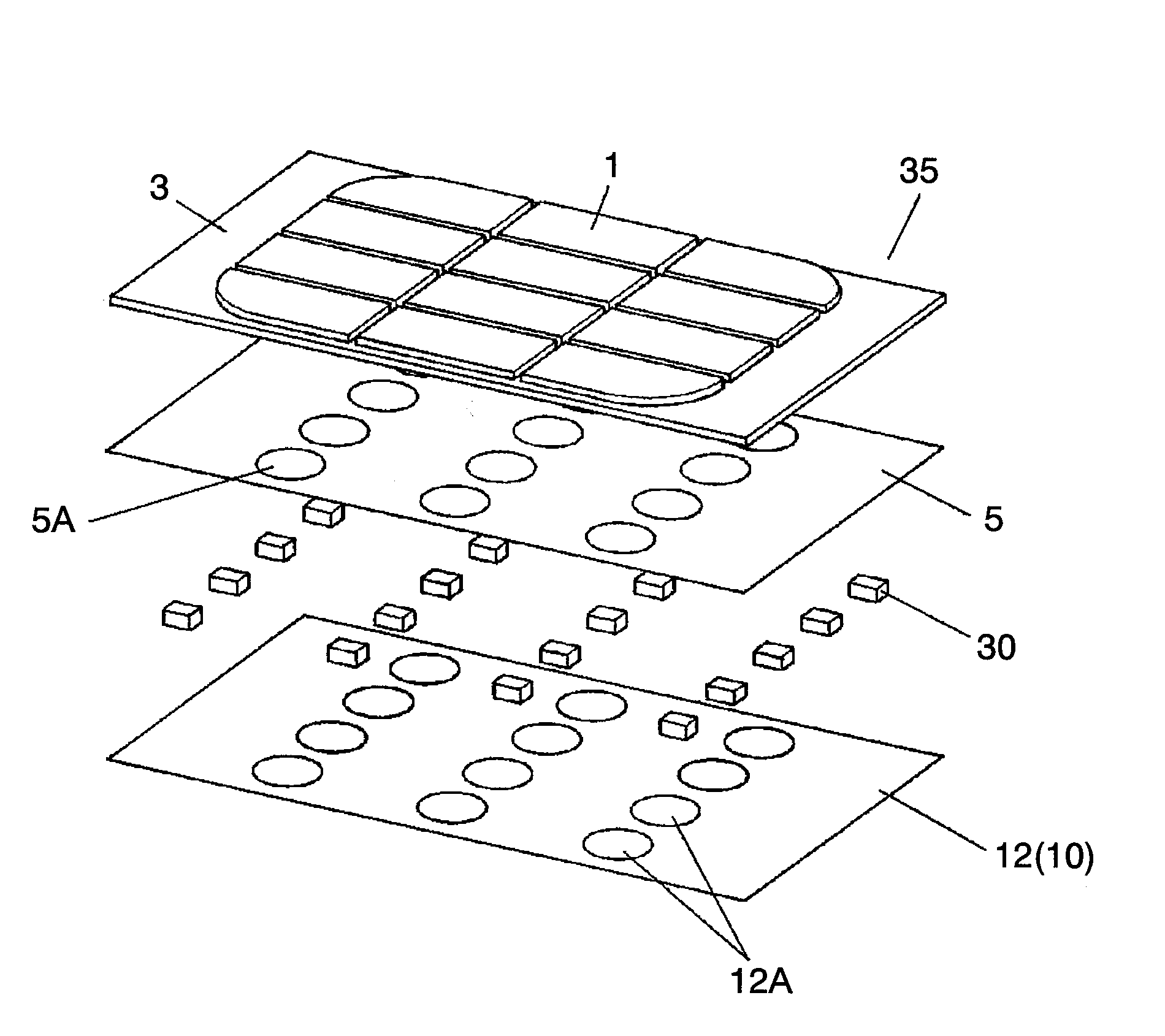
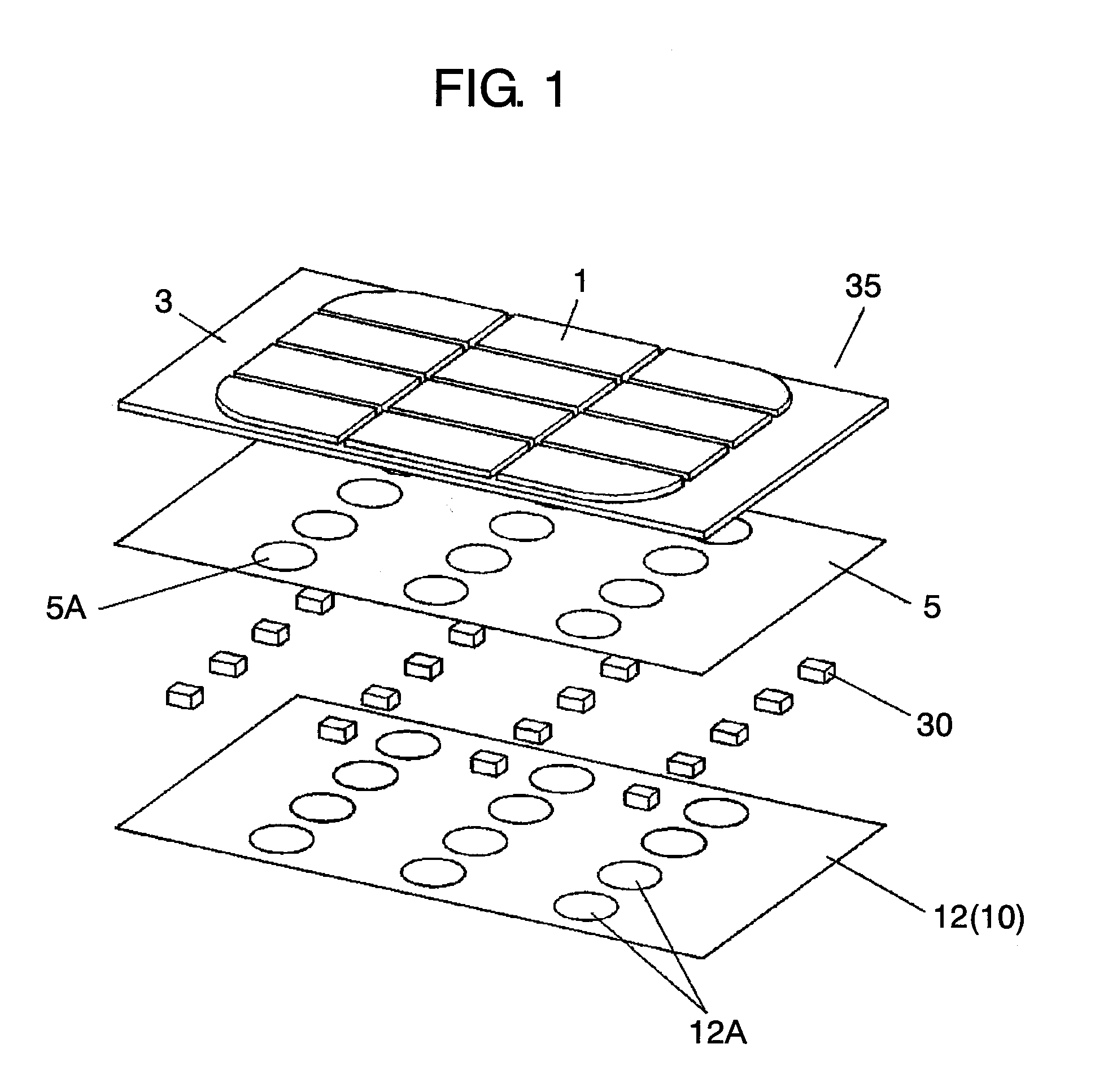
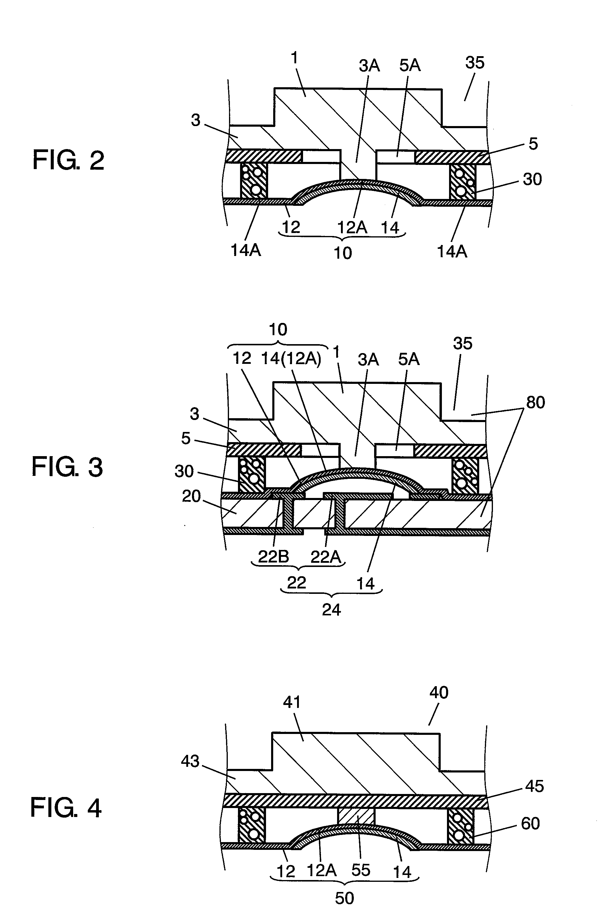
[0034]FIG. 1 is an exploded perspective view of a module unit, a principal component of an input device according to the first exemplary embodiment of the present invention, FIG. 2 is a sectional view of the module unit for the input device according to the first exemplary embodiment, and FIG. 3 is a sectional view of a complete input device including a wiring board and the module unit shown in FIG. 2.

[0035]Referring now to FIG. 1 to FIG. 3, description is provided of a main structure of input device 80 according to the first exemplary embodiment of this invention.

[0036]Module unit 35 has a structure formed integrally with actuating key portions 1, movable contacts 14, cushioning member 30 and protruding portions 3A. Movable contacts 14 are disposed under actuating key portions 1, and actuated by a push-on operation of actuating key portions 1. Cushioning member 30 of a sponge-like material is disposed on a space between a lower surface of actuating key portions 1 and an upper surfa...

second exemplary embodiment

[0063]FIG. 4 is a sectional view of a module unit, a principal component of an input device according to the second exemplary embodiment of the present invention, and FIG. 5 is a sectional view of a complete input device including a wiring board and the module unit shown in FIG. 4.

[0064]Input device 85 of this second exemplary embodiment is similar to input device 80 of the first exemplary embodiment illustrated above, wherein it is assembled simply by mounting pre-integrated module unit 40 onto wiring board 20. Input device 85 of this exemplary embodiment differs from input device 80 of the first exemplary embodiment only in minor details of the components such as key mat 43, capacitive sensor 45 and movable contact assembly 50 that compose module unit 40. Description is therefore provided mainly of the different portions of input device 85, and details will be skipped of certain components having same structures and denoted by the same reference marks as those of the first exempla...

third exemplary embodiment

[0077]FIG. 6 is a sectional view showing a part of the module unit of the first exemplary embodiment referred to in describing a manufacturing method thereof according to the third exemplary embodiment of the present invention, FIG. 7 is another view of the part of the module unit associated with the same manufacturing method, and FIG. 8 is still another view of the part of the module unit associated with the same manufacturing method.

[0078]Description is provided in this third exemplary embodiment of a method of manufacturing module unit 35, which constitutes input device 80 illustrated in the first exemplary embodiment.

[0079]The manufacturing method of module unit 35 for input device 80 mainly comprises the following steps.

[0080]The first step is to prepare capacitive sensor 5 and movable contact assembly 10, and print a resin paste mixed with a foaming agent on one of capacitive sensor 5 and movable contact assembly 10 in a prescribed pattern corresponding to an arrangement of cu...


PUM


Abstract

An input device comprises a wiring board having stationary contacts and a module unit placed on the wiring board. The module unit has a structure formed integrally with actuating key portions, movable contacts, cushioning members and protruding portions. The movable contacts are disposed under the actuating key portions, and actuated by a push-on operation of the actuating key portions. The cushioning members are disposed in a space between a lower surface of the actuating key portions and an upper surface of a movable contact retainer bearing the movable contacts to make the space shrinkable when subjected to the push-on operation whereas it maintains an uniform height when not subjected to the push-on operation. The protruding portions depress top center portions of the movable contacts. The input device includes switch elements, each comprising the movable contact and the stationary contact, and the switch element is actuated by the push-on operation on the actuating key portion.

Description

FIELD OF THE INVENTION[0001]The present invention relates to input devices constituting input operation units of various electronic apparatuses and a method of manufacturing module units for the input devices.BACKGROUND OF THE INVENTION[0002]Many input devices used widely as input operation units of various electronic apparatuses such as mobile telephones are equipped with push button type input means, and these input devices are so constructed as to accept entry of telephone numbers and the like through operation of the input means.[0003]With the well-established infrastructure of the Internet communications in recent years, Internet web-pages are frequently browsed even with mobile telephones, which have given rise to the need for the mobile telephones to have the function of moving a cursor freely in a display.[0004]The need to perform the above operating function has yielded new designs of input devices of such a structure that comprises a combination of a coordinate input devic...

Claims


Application Information

Patent Timeline
Patent Type & Authority Applications(United States)
IPC IPC(8): G06F3/041
CPCG06F3/0202G06F3/0213G06F3/044H01H13/807H01H2003/0293H01H2205/016H01H2207/01H01H2207/014H01H2215/036H01H2225/002H01H2225/03H01H2239/006
Inventor TATEHATA, NAOKI
Owner PANASONIC CORP
Why Eureka
Try Eureka