Discharge Rate Control Method for Ink-Jet Printer, Ink Spread Inspecting Method, and Oriented Film Forming Method

a technology of inkjet printer and ink spread inspection, which is applied in the direction of liquid surface applicators, coatings, instruments, etc., can solve the problems of inability to adjust, complex control system, and inability to control the print head, so as to avoid contamination from the work environment, prevent unnecessary forming of oriented films, and ensure inspection the effect of quality

Active Publication Date: 2008-12-18
ISHII HYOKI
View PDF6 Cites 62 Cited by
  • Summary
  • Abstract
  • Description
  • Claims
  • Application Information

AI Technical Summary

Benefits of technology

[0052]According to such apparatus, unnecessary forming of oriented film can be prevented since the ink-jet nozzle will not be moved to the film forming area for oriented film before the ink-jet nozzle is being determined as normal by inspection.
[0053]In addition, the inspecting area includes a transparent body disposed below the ink-jet nozzle, an image recognition camera reading the impacted droplet pattern from below the transparent body, a comparison means comparing the droplet pattern read by the image recognition camera and a normal pattern stored in advance, and an evaluating means evaluating if a result from the comparison means is normal or abnormal. Therefore, the data of the impacted droplet pattern read from the under surface of the transparent object by the image recognition camera and the data stored in advance are compared to determined if the droplet pattern is within the predetermined range. As a result, since no physical agent is within the discharging range, contamination from the work environment is avoided and inspection can be performed reliably.
[0054]Moreover, in the inspecting area, the droplet pattern and the data stored in advance are compared, and a choking of nozzle is determined and displayed when the droplet pattern is not in a predetermined position, a skewed in the flight of droplet is determined and displayed when a position of the droplet pattern is deviated from a predetermined position, and a discharge rate of the ink-jet nozzle is determined and displayed as more than or less than a preset discharge rate when the droplet pattern is larger or smaller than a predetermined size. Therefore, defective oriented film material or ink-jet nozzle can be easily identified and repaired.
[0055]As described above, according to the discharge rate control method and apparatus for the ink-jet printer related to the present invention for solving the first technical problem, ink is discharged on the coating article with non ink-absorbent characteristic. The film thickness of the film corresponding to the ink discharge position of each nozzle is then measured, and thereafter differences between the results obtained indicating the actual film thickness and a target value indicating a target film thickness are determined according to the ink discharge position of each nozzle, and correction of the discharge rate of ink from each nozzle is performed by increasing or decreasing the discharge rate of ink. As a result, unfavorable influence on the amount of data and the control system of the print head, and prevention of the shortening of ink coating time are avoided, and the discharge rate of ink discharged on the coating article from each nozzle can be kept uniform. Therefore, the needs of increasing the coating width in recent years can be met while maintaining a uniform ink coating.
[0056]According to the ink spread inspecting method and apparatus related to the present invention for solving the second technical problem, by comparing the periphery of the cluster of ink droplets, formed by impacting ink droplets on the coating article by discharging the ink droplets a plurality times such that they overlap each other, with the periphery of an ink droplet formed by discharging and impacting the ink droplet on the coating article only once, the amount of light reflected or refracted from the periphery is more than that reflected or refracted from other portions. Therefore, the periphery of the cluster of ink droplets can be clearly identified visually and the ink spread can be accurately determined, and hence a high quality film with a uniform thickness can be formed on the coating article. Moreover, since the film forming process can be performed by continuously discharging ink after determining that the spread is adequate, high grade products with high quality film formed on the coating article can be mass produced, and production yield can be improved.
[0057]According to the oriented film forming method and apparatus related to the present invention for solving the third technical problem, since material can be supply and nozzle adjusted promptly by displaying defective ink-jet nozzle from droplet condition and responding in advance, wastage of material can be prevented, and yield of the factory improved.

Problems solved by technology

Under such circumstances, even by adjusting the applied voltage of each nozzle on the print head, which ought to achieve uniform film thickness as described above, various problems exist in the adjustment itself.
This inevitably leads to an extremely expensive print head, and the system that controls the print head will also becomes complicated and expensive.
Further, the amount of information of the control system will enormously increase, hence creating problems such as an inappropriate decrease in coating speed of ink from each nozzle.
Moreover, even by respectively adjusting the applied voltage of each nozzle in the existing ink-jet printer to achieve a uniform coating of ink droplets, there is limitation in the precision of applied voltage and achieving sufficient uniformity is difficult.
However, this is virtually impossible to realized, and even if realized, the control system will be further complicated and the amount of information overwhelming, consequently leading to a further decrease in the coating speed of ink.

Method used


Image

  • Discharge Rate Control Method for Ink-Jet Printer, Ink Spread Inspecting Method, and Oriented Film Forming Method
  • Discharge Rate Control Method for Ink-Jet Printer, Ink Spread Inspecting Method, and Oriented Film Forming Method
  • Discharge Rate Control Method for Ink-Jet Printer, Ink Spread Inspecting Method, and Oriented Film Forming Method

Examples


first embodiment

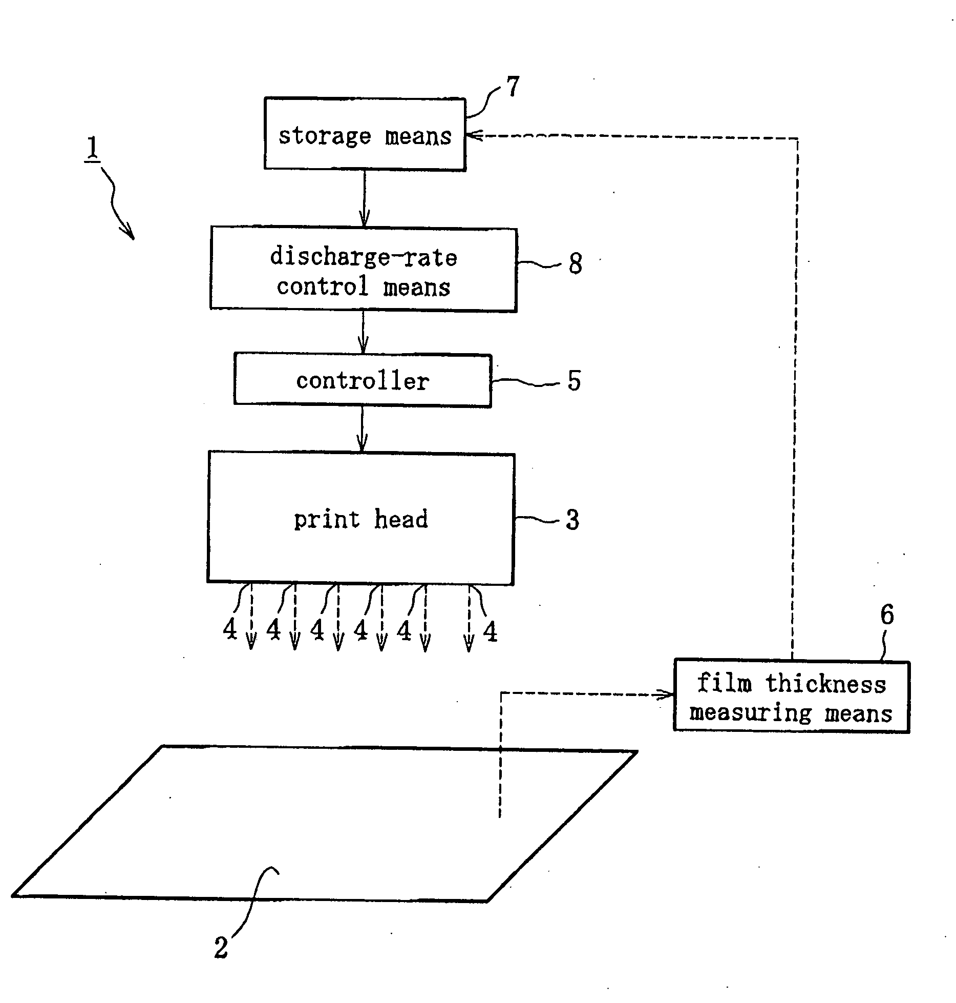
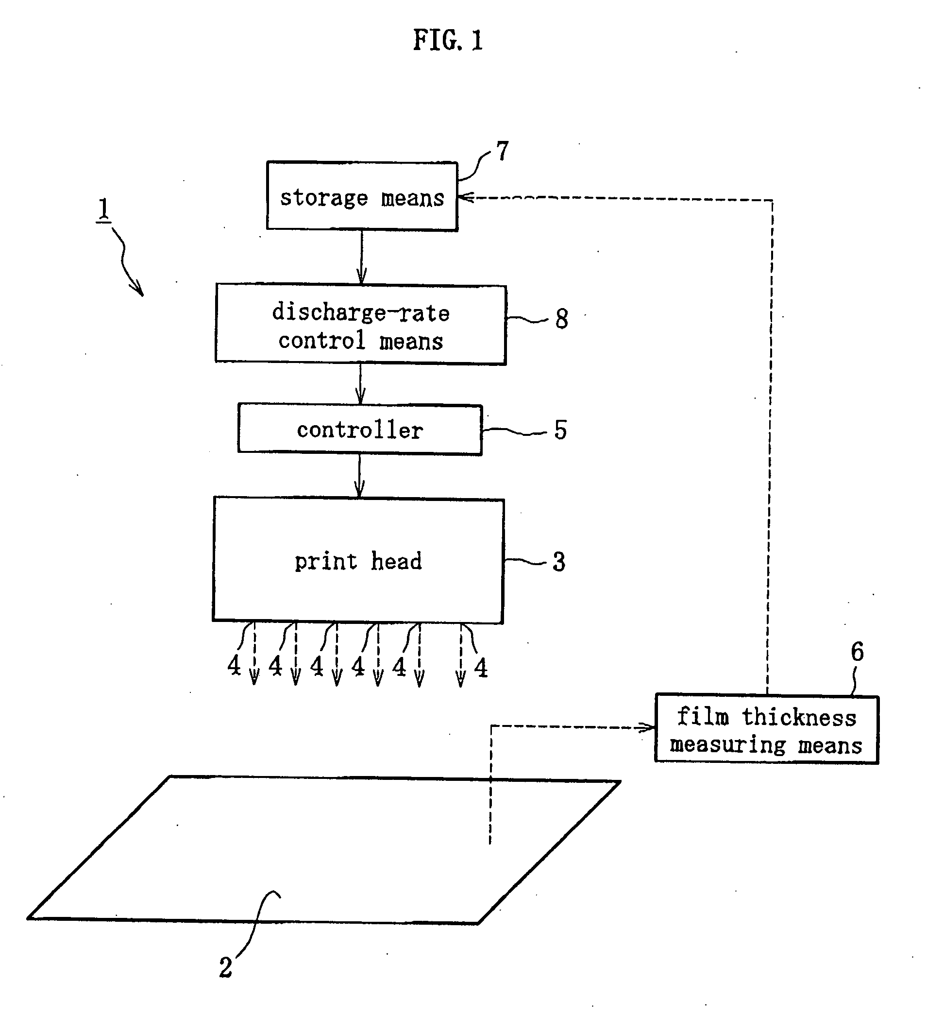
[0096]FIGS. 1 to 11 are examples representing the first embodiment of the present invention. As represented in FIG. 1, a discharge-rate control apparatus 1 of an ink-jet printer includes, as main components, a transparent glass substrate 2 used in a liquid crystal display equipment and having non ink-absorbent characteristic, a controller 5 for controlling the quantity of ink discharged from a plurality of nozzles 4 of a print head 3, and a film thickness measuring means 6 for measuring, with respect to the discharge position of each nozzle 4, the thickness of a film formed on the glass substrate 2 by the ink discharged from the print head 3. The discharge-rate control apparatus 1 further includes a storage means 7 for storing correction data corresponding to the difference between a target film thickness and a film thickness determined by the film thickness measuring means 6 at the ink discharge position of each nozzle 4, and a discharge-rate correction means 8 that retrieves the c...

second embodiment

[0105]FIGS. 12 to 18 are examples representing the second embodiment of the present invention. FIG. 12(a) is a schematic plan view representing components of an ink-spread inspecting apparatus including an ink-jet print head 1, a transparent-like glass substrate 2 drawn in solid lines and serving as a coating article before being coated by ink droplet, and the glass substrate 2 drawn in dotted lines after being coated by ink droplets (a cluster of ink droplets 3), and FIG. 12(b) is a schematic side view representing each component 1, 2 in the same state. FIG. 13 is a schematic side view representing an arrangement of an inspecting camera 4 and a plurality of lightings 5, 6, which are components of the ink-spread inspecting apparatus.

[0106]In the second embodiment, as represented in FIGS. 12(a), (b), when a glass substrate 2 below an ink-jet print head 1, which is being maintained in a fixed position, is moved in the direction of the arrow, ink droplets are discharged on the surface ...

third embodiment

[0112]FIGS. 20 to 26 are examples representing the third embodiment of the present invention. FIG. 20 is a schematic side view of an ink-jet type print head discharge inspecting apparatus. FIG. 21 is a top view of FIG. 20, FIG. 22 is a block diagram illustrating operation of main components of the third embodiment, FIG. 23 is a main-components flowchart of FIG. 22, FIG. 24 represents droplet patterns when choking of ink-jet nozzles is being detected, FIG. 25 represents droplet patterns when skewed discharging of ink-jet nozzles is being detected, and FIG. 26 represents droplet patterns when the quantity of droplets from ink-jet nozzles is being detected.

[0113]An oriented film forming apparatus 1 includes an inspecting area 3 in which droplets of oriented film material are discharged by an ink-jet group 2 composed of 8 ink-jet nozzles (A, B, C, D, E, F, G, H) and anomalies of the ink-jet nozzles are inspected according to the pattern of the droplets Ap, Bp, Cp, Dp, Ep, Fp, Gp, Hp, an...


PUM

PropertyMeasurementUnit
thicknessaaaaaaaaaa
surface tensionaaaaaaaaaa
thicknessaaaaaaaaaa

Abstract

Discharge rate control method for ink-jet printer 1 including film forming step forming film B on coating article 2 with non ink-absorbent characteristic by discharging ink on coating article 2 from a plurality of nozzles 4 of print head 3, film thickness measuring step measuring film thickness of film B, corresponding to ink discharge position of each nozzle 4, formed on coating article 2 in film forming step, and discharge rate correcting step correcting discharge rate of ink from each nozzle 4 by increasing or decreasing discharge rate based on difference between target film thickness Ba and film thickness at ink discharge position of each nozzle 4 measured in film thickness measuring step.

Description

FIELD OF THE INVENTION[0001]The present invention relates to a technique for maintaining the uniformity of discharge rate of ink, between each nozzle, on coating article from a plurality of nozzles on a print head of an ink-jet printer, a technique for inspecting ink spread, and a technique for forming oriented film on a glass substrate using such ink.BACKGROUND OF THE INVENTION[0002]In recent years, in addition performing printing by an ink-jet printer on substrate composed of paper, fabric, plastic, ceramic or the like, ink-jet printer is also being used when forming oriented film on transparent glass substrate for equipments such as liquid crystal display equipment, or when coating color filter on transparent glass substrate in organic EL display equipment. Specifically, in the case of liquid crystal display equipment, oriented film material such as transparent PI ink (transparent polyimide ink) or transparent UV ink is discharged and coated on glass substrate (see patent documen...

Claims


Application Information

Patent Timeline
Patent Type & Authority Applications(United States)
IPC IPC(8): B41J29/38
CPCG02F1/133711B05B12/084B05B15/50B05C5/00B41J2/01G02F1/13
Inventor NAKANO, TERUYUKIKOZAWA, YASUHIRO
Owner ISHII HYOKI
Why Eureka
Try Eureka