Urban pipe network sludge treatment method and system
A technology for sludge treatment and pipe network, applied in the field of sludge treatment method and system for urban pipe network, can solve the problems of limited applicable conditions, high construction cost, separation of drainage and pollution control functions, etc., to avoid harsh working environment and work efficiency. High and wide range of effects
- Summary
- Abstract
- Description
- Claims
- Application Information
AI Technical Summary
Problems solved by technology
Method used
Image
Examples
Embodiment 1
[0043] The urban pipe network sludge treatment method is characterized in that it comprises the following steps:
[0044] 1) Inspection well cleaning: clean up the inspection wells upstream and downstream of the dredging pipe section;
[0045] 2) Block upstream:
[0046] 3) Wear the traction rope: pass the traction rope through the upstream and downstream inspection wells and the pipelines to be dredged, and then connect it to the winch system on the ground;
[0047] 4) Pipeline survey: Connect the surveyor used for pipeline survey with the traction rope of the winch system, put the surveyor into the pipeline to be dredged through the traction rope, and conduct survey on the pipeline to be dredged. After the survey is completed, pass The traction rope lifts the surveyor to the ground;
[0048] 5) Silt cleaning: first connect the digging device with the traction rope of the hoisting system, put the digging device into the pipeline to be dredged through the traction rope, and ...
Embodiment 2
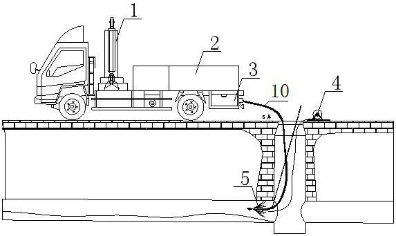
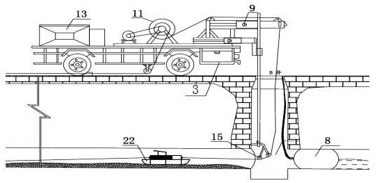
[0051] like Figure 1 to Figure 4 As shown, it is improved on the basis of Example 1. In the step 1), the inspection wells upstream and downstream of the dredging pipe section are cleaned with auxiliary work vehicles, and different types of silts are used according to the type and degree of consolidation in the inspection wells. Catch and dig. Start the hydraulic grab 1, the hydraulic grab 1 grabs the water-containing sediment, and the muddy water flows out from the lower tank of the hydraulic grab 1 and the leakage holes on both sides to realize the separation of the muddy water. Turn to and lift to ground again, pour into mud storage bin 2. When hardened sediment is encountered, the grab arm rotates to cut and stir the sediment, and then grabs and lifts it; when the on-board sludge storage tank is full, the storage tank is lifted by the hydraulic bottom shaft, and the sludge is poured into the sludge transport vehicle .
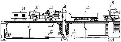
[0052] In described step 2), use air bag 8 to bloc...
Embodiment 3
[0059] like Figure 4 As shown, it is improved on the basis of Example 1 or Example 2. After the sludge cleaning in the step 5) is completed, the sludge treatment vehicle is used to complete the sludge reduction treatment and water recovery of the cleaned sludge, and the sludge treatment The car includes a coarse grid machine 17, a cyclone 18, a settling chamber 19, a belt filter press 20 and a circulating water collection tank 21. The mud in the pipeline enters the coarse grid machine 17 through a suction pump, and then passes through the cyclone. 18 screening, settling chamber 19 flocculation, belt filter press 20 filter press dehydration process, complete sludge reduction treatment and water reuse.
[0060] Then the dried silt is transported out with the silt transport unit, and the silt transport unit mainly consists of a silt transport flatbed truck and a trailer head 6. The box body of the sludge transport flatbed truck is a funnel-type sewage storage box 7. In order to...
PUM
 Abstract
Description
Claims
Application Information
 - R&D
- Intellectual Property
- Life Sciences
- Materials
- Tech Scout
- Unparalleled Data Quality
- Higher Quality Content
- 60% Fewer Hallucinations
Browse by: Latest US Patents, China's latest patents, Technical Efficacy Thesaurus, Application Domain, Technology Topic, Popular Technical Reports.
© 2025 PatSnap. All rights reserved.Legal|Privacy policy|Modern Slavery Act Transparency Statement|Sitemap|About US| Contact US: help@patsnap.com


