Image forming method and image forming apparatus

a technology of image forming and forming apparatus, which is applied in the direction of digitally marking record carriers, instruments, visual presentation using printers, etc., can solve the problems of inability to use printers using serial heads, uneven stripe, and the pattern of stripe unevenness may become more complex, so as to optimally cope with stripe unevenness

Active Publication Date: 2008-12-18
FUJIFILM CORP
View PDF2 Cites 12 Cited by
  • Summary
  • Abstract
  • Description
  • Claims
  • Application Information

AI Technical Summary

Benefits of technology

[0021]According to the image forming apparatus, the comparing unit identifies the non-ejection color and the line position containing the non-ejection nozzle thereof, and image formation is performed such that a special color conversion table corresponding to the non-ejection color is applied at the identified non-matching colored portion. Therefore, it is possible to optimally cope with the stripe unevenness resulting from t

Problems solved by technology

However, in the case of the line head, from the viewpoint of efficiency, since all the colors are usually rendered during one transport, a compensation method that compensates or obviates the stripe unevenness by using inks of the same color in a plurality of scanning operations, as used in the printer using the serial head is not usable.
In the disclosed technique, there is a possibility that the above-described non-ejection

Method used


Image

  • Image forming method and image forming apparatus
  • Image forming method and image forming apparatus
  • Image forming method and image forming apparatus

Examples


Embodiment Construction

[0029]Hereinafter, an ink jet image forming apparatus related to an image recording method according to the present invention will be described with reference to the accompanying drawings.

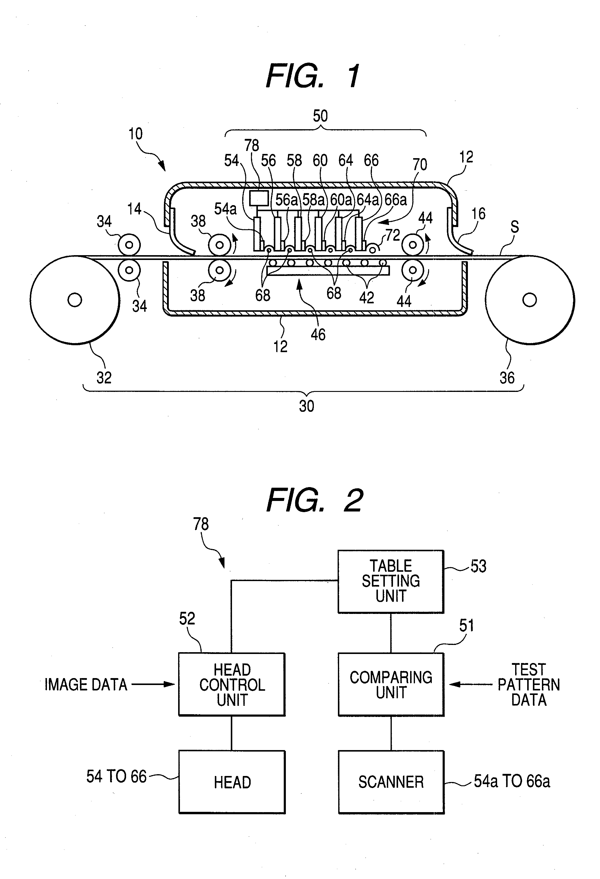
[0030]FIG. 1 is a schematic view of an active energy ray curable ink jet image forming apparatus according to an embodiment of the present invention.

[0031]The active energy ray curable ink jet image forming apparatus 10 uses, as a liquid functional material of active energy ray curable type, a UV curable ink that is cured by irradiation of ultraviolet rays.

[0032]In addition, the present embodiment is directed to an image forming apparatus that uses an active energy ray curable ink; however, ink that can be used in the present invention is not limited to this, but other types of ink, generally one which can be applied to an ink jet method of a line head may be used.

[0033]As shown in FIG. 1, in a casing 12 of an active energy ray curable ink jet recording apparatus 10, a web-like recording medium S w...


PUM


Abstract

An image forming method that forms an image by using inks of secondary chromatic colors based on an input image, the method including: forming a test pattern that uses a color chart with the entire secondary chromatic colors of the used inks by using a normal color conversion table for converting a first color space of the input image into a second color space of the formed image; comparing data obtained by scanning the formed test pattern with second color space data of the test pattern, and identifying a non-matching color portion as a non-ejection color and a line position containing a non-ejection nozzle thereof; preparing a special color conversion table, the special color conversion table being provided for each omission ink; and setting and using the special color conversion table for an omission ink corresponding to the non-ejection color at the line position containing the identified non-ejection nozzle.

Description

BACKGROUND OF THE INVENTION[0001]1. Field of the Invention[0002]The present invention relates to an image forming method that performs image formation by an ink jet head that uses a plurality of line heads containing therein ink of secondary chromatic colors.[0003]2. Background Art[0004]In ink jet printers, there are a printer in which uses a short serial head and performs recording while scanning the head in the width direction of a recording medium, and a printer using a line head in which recording elements are arranged over the entire areas in the width direction intersecting the transport direction of a recording medium. In the printer using such a line head, it is not necessary to equip a transport system such as a carriage for scanning the short serial head, and control related to the movement of the carriage and complicated scanning control of the recording medium are not necessary. Furthermore, since only the recording medium is moved, it is possible to achieve higher recor...

Claims


Application Information

Patent Timeline
IPC IPC(8): B41J29/393
CPCB41J29/393
Inventor KONDO, HIROKAZU
Owner FUJIFILM CORP
Why Eureka
Try Eureka