Driving Support System And Vehicle

a technology of supporting system and support system, which is applied in the field of driving support system and vehicle, can solve the problem of insufficient visibility support and other problems

Inactive Publication Date: 2008-12-18
SANYO ELECTRIC CO LTD
View PDF6 Cites 39 Cited by
  • Summary
  • Abstract
  • Description
  • Claims
  • Application Information

AI Technical Summary

Benefits of technology

[0016]Accordingly, even when the installation position of the camera, the optical axis direction thereof or the like is misaligned, it is possible to display an image in which an influence caused by such misalignment is eliminated or suppressed.

Problems solved by technology

In such cases, sufficient visibility support is not provided since the driver feels something wrong when driving the vehicle while watching a image having such a misalignment or inclination.

Method used


Image

  • Driving Support System And Vehicle
  • Driving Support System And Vehicle
  • Driving Support System And Vehicle

Examples


first example

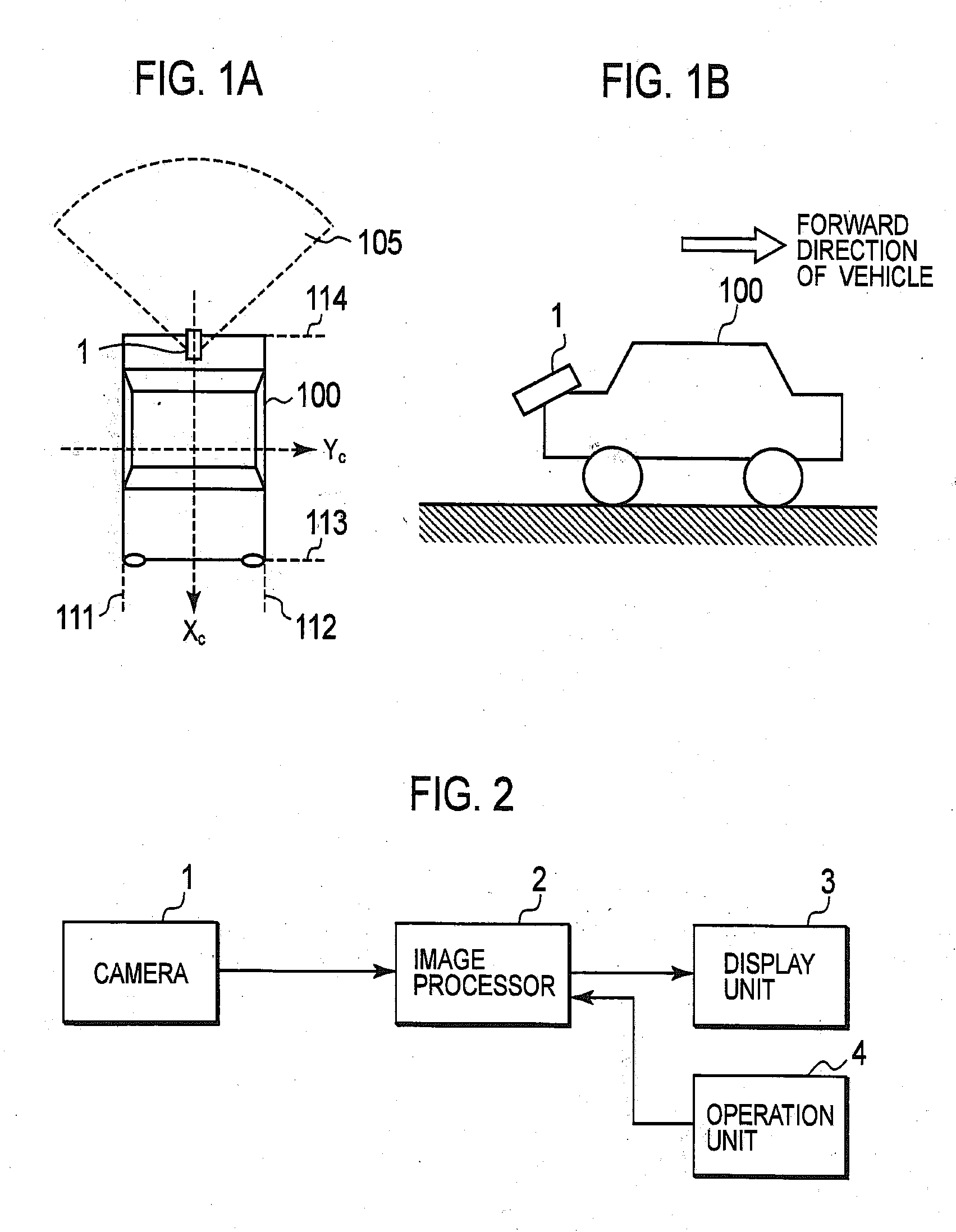
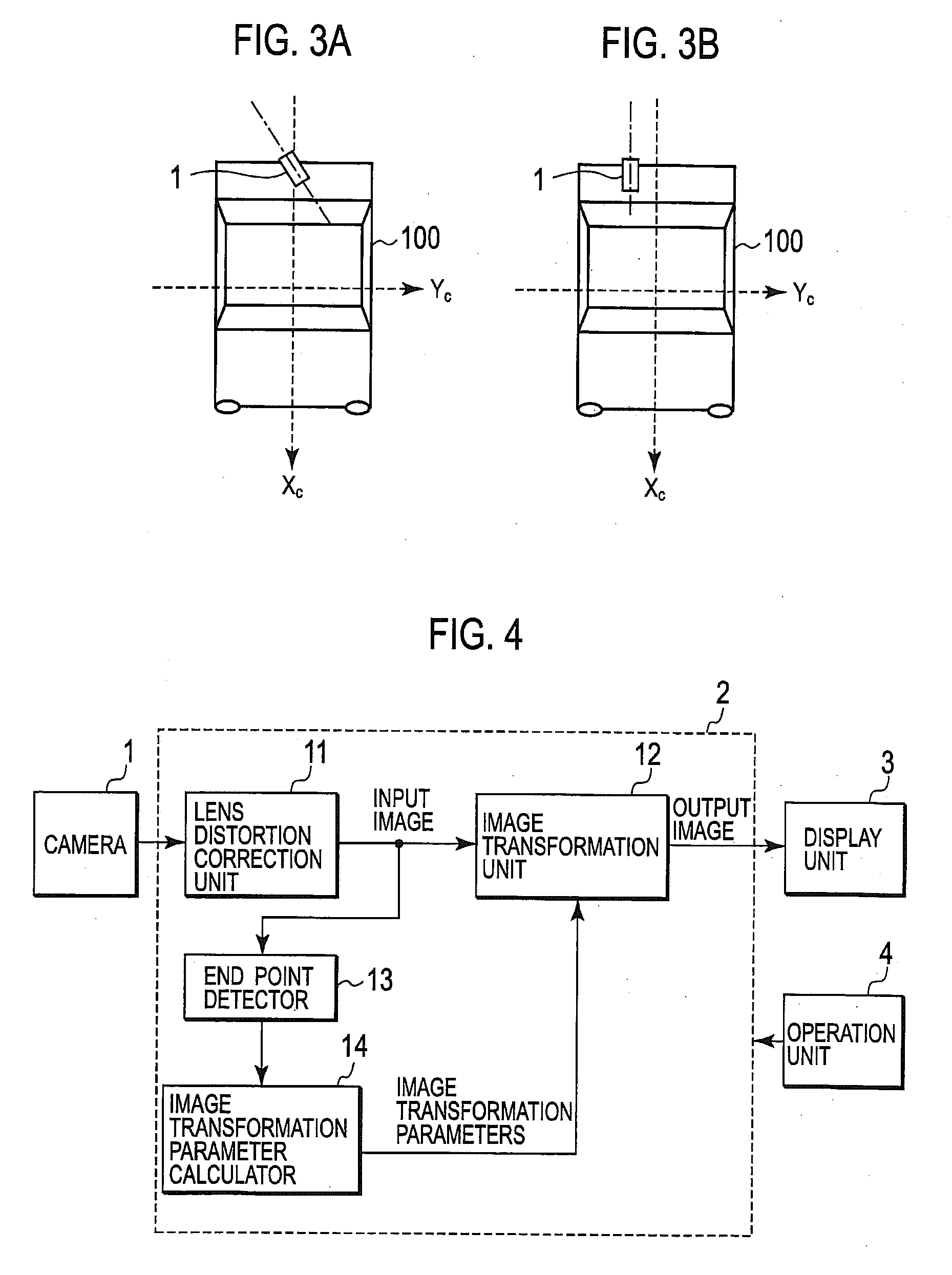
[0051]A first example of the present invention will be described. FIG. 4 is a configuration block diagram of a visibility support system according to the first example. The image processor 2 of FIG. 4 includes components respectively denoted by reference numerals 11 to 14.

[0052]A lens distortion correction unit 11 performs lens distortion correction for the image obtained by capturing the scene with the camera 1 and then outputs the image after the lens distortion correction to an image transformation unit 12 and an end point detector 13. The image outputted from the lens distortion correction unit 11 after the lens distortion correction is hereinafter termed as an “input image.” It should be noted that the lens distortion correction unit 11 can be omitted in a case where a camera having no lens distortion or only a few ignorable amounts of lens distortion is used as the camera 1. In this case, the image obtained by capturing the scene with the camera 1 may be directly transmitted t...

second example

[0096]Next, a second example of the present invention will be described. FIG. 15 is a configuration block diagram of a visibility support system according to the second example. The visibility support system of FIG. 15 includes the camera 1, an image processor 2a, the display unit 3 and the operation unit 4. The image processor 2a includes components denoted by reference numerals 11 to 15, respectively. Specifically, except that an image transformation verification unit 15 is added in the configuration of the visibility support system according to the second example, the configuration is the same as that of the visibility support system according to the first example. Except for this point, both of the visibility support systems are the same. Accordingly, a description will be hereinafter given of only functions of the image transform verification unit 15. The matters described in the first example also apply to the second example unless there is a discrepancy.

[0097]FIG. 16 is a flo...

third example

[0106]Next, a third example of the present invention will be described. FIG. 18 is a configuration block diagram of a visibility support system according to the third example. The visibility support system of FIG. 18 includes the camera 1, an image processor 2b, the display unit 3 and the operation unit 4. The image processor 2b includes components respectively denoted by reference numerals 11, 12, 14, 15, 21 and 22.

[0107]The functions of the lens distortion correction unit 11, the image transformation unit 12, the image transformation parameter calculator 14 and the image transformation verification unit 15 are the same as those described in the first or the second example.

[0108]A procedure of deriving image transformation parameters according to this example will be described with reference to FIG. 19. FIG. 19 is a flowchart showing this procedure of deriving image transformation parameters. First, in step S30, the editing environment of a periphery of the vehicle 100 is set in a ...


PUM


Abstract

Disclosed is a driving support system. With this system, a vehicle including a camera installed thereon is arranged at the center of a parking lot defined by two parallel white lines. End points of the respective white lines are included in the field of view of the camera. While the vehicle is moving forward, first and second editing images are obtained respectively at first and second points different from each other. Two end points of each of the editing images are detected as four feature points in total. Image transformation parameters for causing the center line of the vehicle and the center line of the image to coincide with each other are found on the basis of coordinate values of the four feature points on each of the editing images. An output image is obtained by use of the found image transformation parameters.

Description

CROSS REFERENCE TO RELATED APPLICATION[0001]Applicant claims, under 35 U.S.C. .sctn. 119, the benefit of priority of the filing date of Apr. 18, 2007, of a Japanese Patent Application No. P 2007-109206, filed on the aforementioned date, the entire contents of which are incorporated herein by reference.BACKGROUND OF THE INVENTION[0002]1. Field of the Invention[0003]The present invention relates to a driving support system for supporting the driving of a vehicle. The present invention also relates to a vehicle using the system.[0004]2. Description of the Related Art[0005]Heretofore, a large number of systems for providing visibility support to a driver have been developed. In these systems, a image captured by an on-vehicle camera installed on a rear portion of a vehicle and is displayed on a display provided near the driving seat to provide a good field of view to the driver. In this type of systems, due to the limitation of the structure or the design of the vehicle or an installati...

Claims


Application Information

Patent Timeline
Patent Type & Authority Applications(United States)
IPC IPC(8): H04N7/18
CPCB60R1/00B60R2300/607B60R2300/806B60R2300/8066G06T3/00G08G1/168
Inventor HONGO, HITOSHI
Owner SANYO ELECTRIC CO LTD
Why Eureka
Try Eureka