Laser metrology system and method

a laser metrology and laser technology, applied in the field of laser metrology system and method, can solve the problems of difficult affixing of receivers to production components, difficult to achieve dimensional accuracy, and high cost of indoor gps system, so as to reduce complexity and cost, and expand the potential use of metrology determination.

Active Publication Date: 2008-12-18
NIKON METROLOGY
View PDF3 Cites 73 Cited by
  • Summary
  • Abstract
  • Description
  • Claims
  • Application Information

AI Technical Summary

Benefits of technology

[0007]A laser metrology system for determining the location of a target, and, for example, a production environment is disclosed. A laser projector includes a laser source for projecting a laser beam to a rotating head that directs the laser beam in a lateral direction. A sensor is associated with the laser projector and communicates with a computer that controls the laser metrology system. A sensor senses the laser beam and signals the computer information regarding the laser beam. A reflective target configured to reflect the laser beam projected from the projector in a lateral direction reflects the laser beam toward the sensor in a manner indicative of an angle of the rotating head and the pulse of the laser beam. The computer subsequently determines the location of the target based upon the angle of the rotating head and the pulse of the laser beam. The use of a reflective target to reflect a transmitted laser beam toward a sensor solves the problem associated with the prior art indoor metrology systems by eliminating expensive receivers and wiring associated with the same. Furthermore, the reflective target can be placed just about anywhere inside a production environment, including upon small manufacturing apparatus and components, enabling the indoor metrology system of the present system to determine the precise accuracy of the location of these elements. The reduction of the complexity and the cost associated with the indoor metrology device of the present invention expands the potential use of metrology determination in manufacturing settings that demand a high level of dimensional accuracy.

Problems solved by technology

These indoor GPS systems, particularly the receivers, have proven to be expensive and fragile requiring the construction of complex communication infrastructure with several computers, Ethernet hubs, etc.
The wiring associated with the receiver has proven expensive and difficult to work with in a production environment and makes it difficult to affix the receivers to production components.
Laser scanners include an infrared light transmitter and a retro-reflective prism, but are limited in application.
However, all of these systems have proven to be cost-prohibitive, and not practicable for a production environment.

Method used


Image

  • Laser metrology system and method
  • Laser metrology system and method
  • Laser metrology system and method

Examples


Embodiment Construction

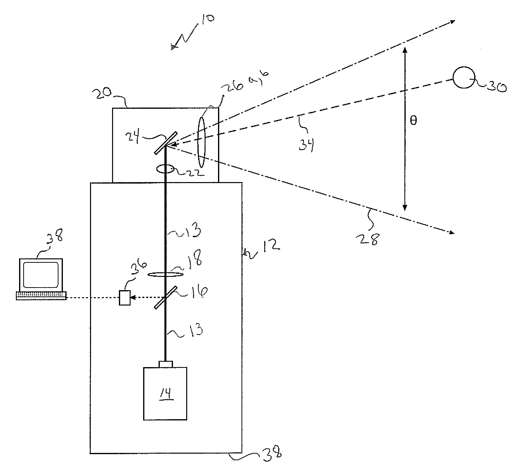
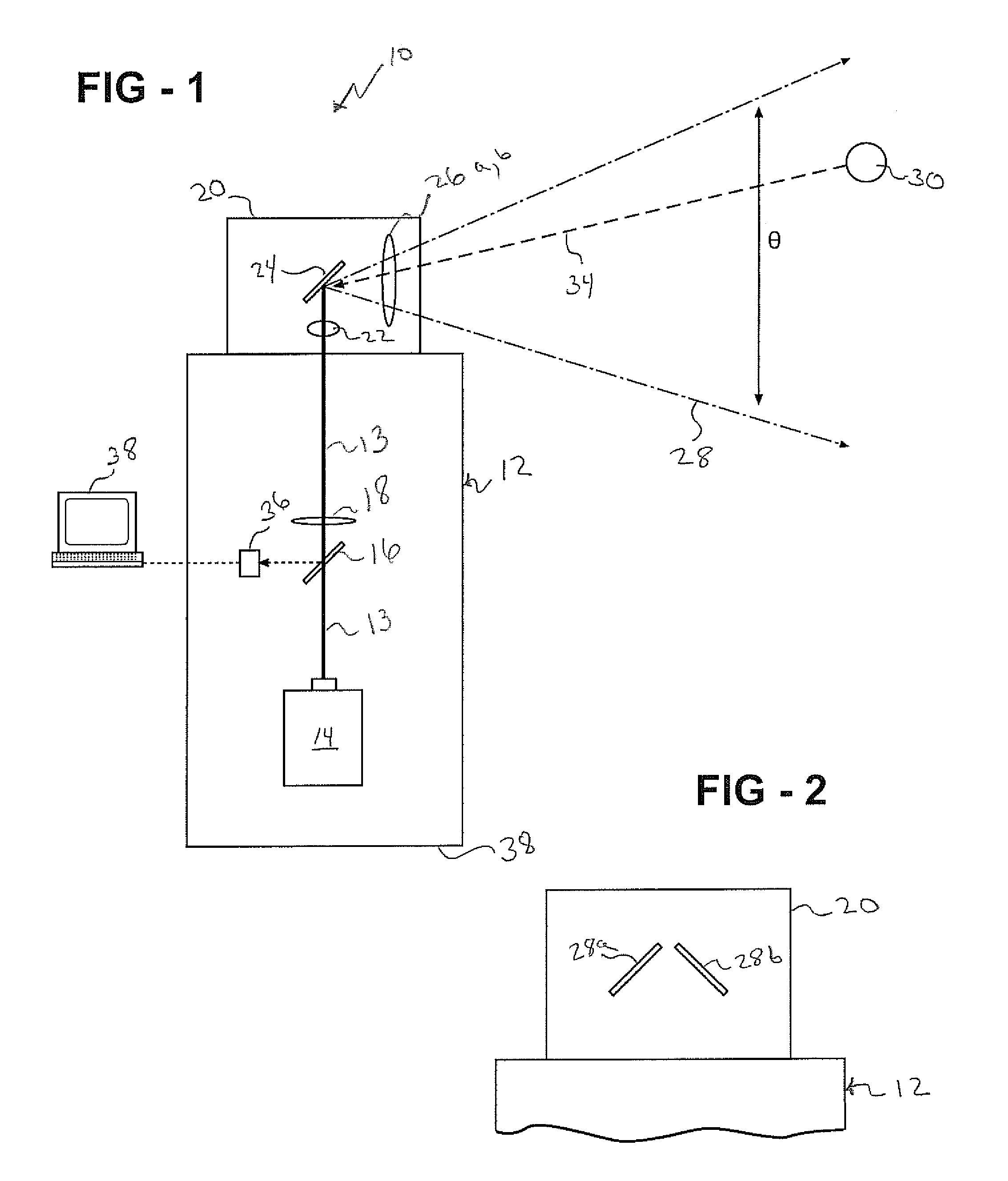
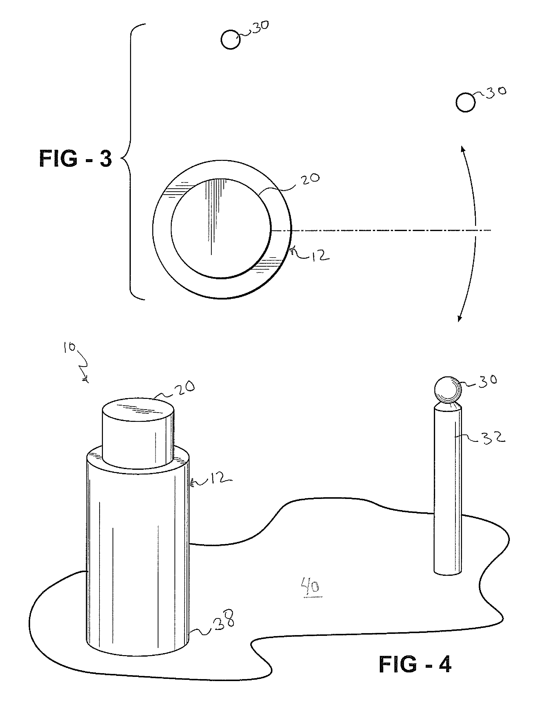
[0013]Referring to FIGS. 1 and 4, an indoor metrology system of the present invention is generally shown at 10. A laser projector 12 includes a laser source 14 capable of producing a laser beam in a known manner. The laser source 14 projects a laser beam, preferably in a vertical direction, through a beam splitter 16, the purpose of which will be explained further below. Subsequent to passing through the beam splitter, the transmitted laser beam 13 passes through a collimator 18 in a known manner to collimate the transmitted laser beam 13.

[0014]The collimator 18 focuses the laser beam 13 into a rotating head 20 that pivots generally upon an axis defined by the laser transmitted beam 13. The transmitted laser beam 13 passes through a head lens 22 and is focused upon a mirror 24 that rotates along with the rotating head 20. In one embodiment of the present invention, the mirror 24 is oriented at an angle obtuse to the axis defined by the transmitted laser beam 13. Therefore, the mirro...


PUM


Abstract

A laser metrology system for determining a location of a target utilizes a laser projector having a laser source for projecting a laser beam. A rotating head directs the laser beam in a lateral direction. A sensor associated with the laser projector is capable of sensing the laser beam. A reflective target is configured to reflect the laser beam projector from the laser source toward the sensor in a manner indicative of the angle of the rotating head and the pulse of the laser beam to determine location of the target.

Description

RELATED APPLICATION[0001]This application claims priority to U.S. Provisional Patent Application Ser. No. 60 / 934,338 filed Jun. 13, 2007.FIELD OF THE INVENTION[0002]This invention relates generally to a method and apparatus for generating position-related data and orientation of a target in a three-dimensional space.BACKGROUND OF THE INVENTION[0003]Modern manufacturing standards demand ever-increasing dimensional accuracy in a production setting. In order to meet these modern demands, such as, for example, assembly tolerances of less than one millimeter, efforts have been made to accurately determine the location of various manufacturing components in a three-dimensional space. Various dimensional metrology apparatus systems are available that provide a method in which to determine the dimensional location of manufacturing components inside a production setting.[0004]One such example is a product provided by Metris USA, Inc., that offers an “indoor GPS” system as disclosed, for exam...

Claims


Application Information

Patent Timeline
Patent Type & Authority Applications(United States)
IPC IPC(8): G01B11/00
CPCG01C15/002G01S7/4812G01S17/42
Inventor RUEB, KURT D.
Owner NIKON METROLOGY
Why Eureka
Try Eureka