
Image taking apparatus and image taking method

a technology of image taking apparatus and image, which is applied in the direction of camera body details, instruments, exposure control, etc., can solve the problems of wasteful consumption of power consumption, achieve the effect of reducing power consumption, reducing power consumption, and efficiently using c-a

Inactive Publication Date: 2008-12-18
FUJIFILM CORP
View PDF8 Cites 7 Cited by
  • Summary
  • Abstract
  • Description
  • Claims
  • Application Information

AI Technical Summary

Benefits of technology

[0006]However, the camera disclosed in Japanese Patent Application Laid-Open No. 2003-107326 has a drawback in that power consumption is wastefully consumed since C-AF operates when a photographer conducts camera works such as for a position, an angle or the size of a shot of a subject. In view of such circumstances, it is an object of the present invention to provide an image taking apparatus and an image taking method which can efficiently use C-AF and reduce the power consumption.
[0008]According to the first aspect, C-AF can be used efficiently and the power consumption can be depressed.
[0014]According to the aspect, the C-AF can be used efficiently and the power consumption can be depressed.
[0015]According to the present invention, the amount of camera shakes is detected and operation or non-operation of the C-AF is controlled, so that an image taking apparatus and an image taking method can be provided which can efficiently use C-AF and reduce the power consumption.

Problems solved by technology

However, the camera disclosed in Japanese Patent Application Laid-Open No. 2003-107326 has a drawback in that power consumption is wastefully consumed since C-AF operates when a photographer conducts camera works such as for a position, an angle or the size of a shot of a subject.

Method used


Image

  • Image taking apparatus and image taking method
  • Image taking apparatus and image taking method
  • Image taking apparatus and image taking method

Examples


first embodiment

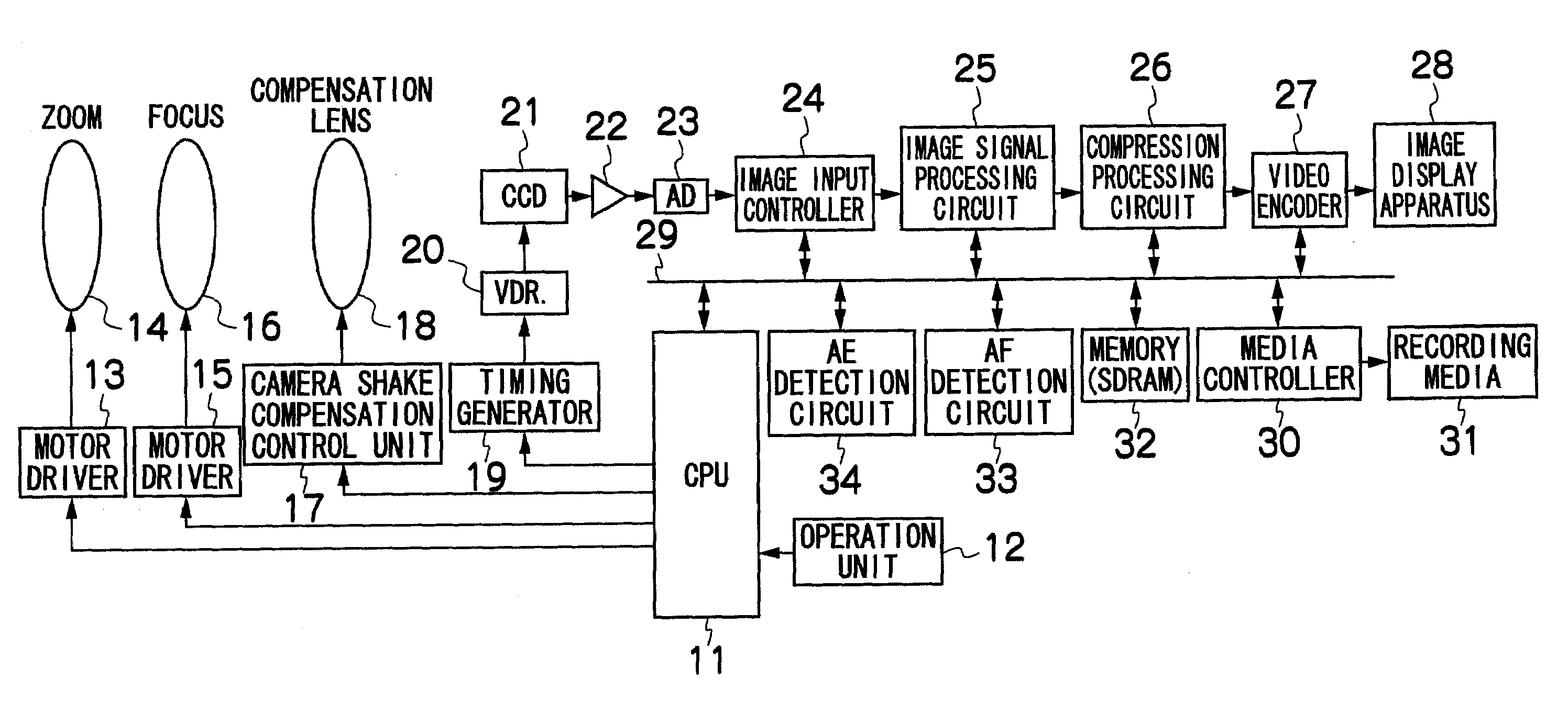
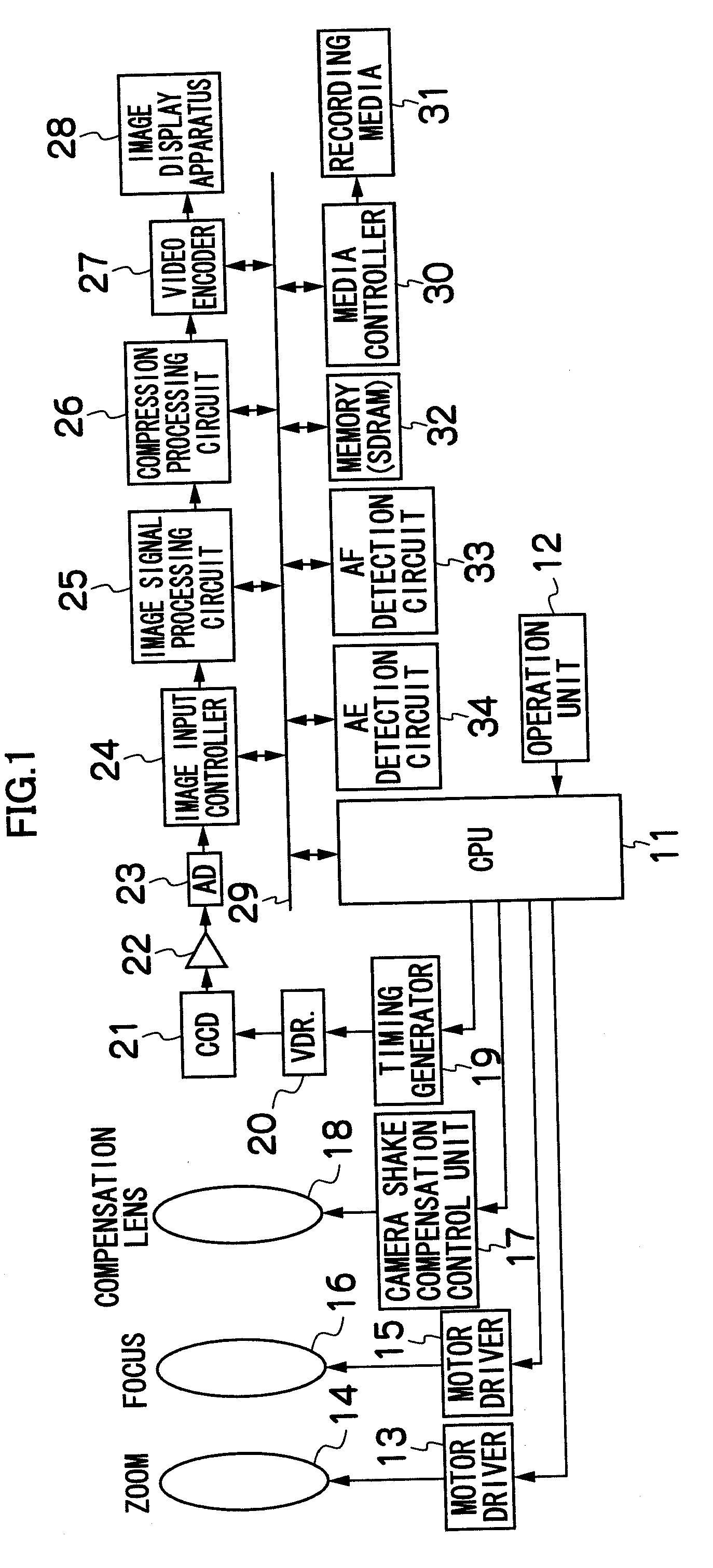
[0023]FIG. 1 is a block diagram showing the electric configuration according to a first embodiment of a digital camera to which the present invention is applied.

[0024]As shown in FIG. 1, a digital camera 10 according to this embodiment comprises a CPU 11, an operation unit 12, a zoom lens motor driver 13, a zoom lens 14, a focus lens motor driver 15, a focus lens 16, a camera shake compensation control unit 17, a camera shake compensation lens 18, a timing generator 19, a CCD driver 20, a CCD image sensor 21, an analog signal processing unit 22, an A / D converter 23, an image input controller 24, an image signal processing circuit 25, a compression processing circuit 26, a video encoder 27, an image display apparatus 28, a bus 29, a media controller 30, a recording media 31, a memory (SDRAM) 32, an AF detection circuit 33, an AE detection circuit 34 and the like.

[0025]The respective units operate through control by the CPU 11. The CPU 11 controls the respective units of the digital c...


PUM


Abstract

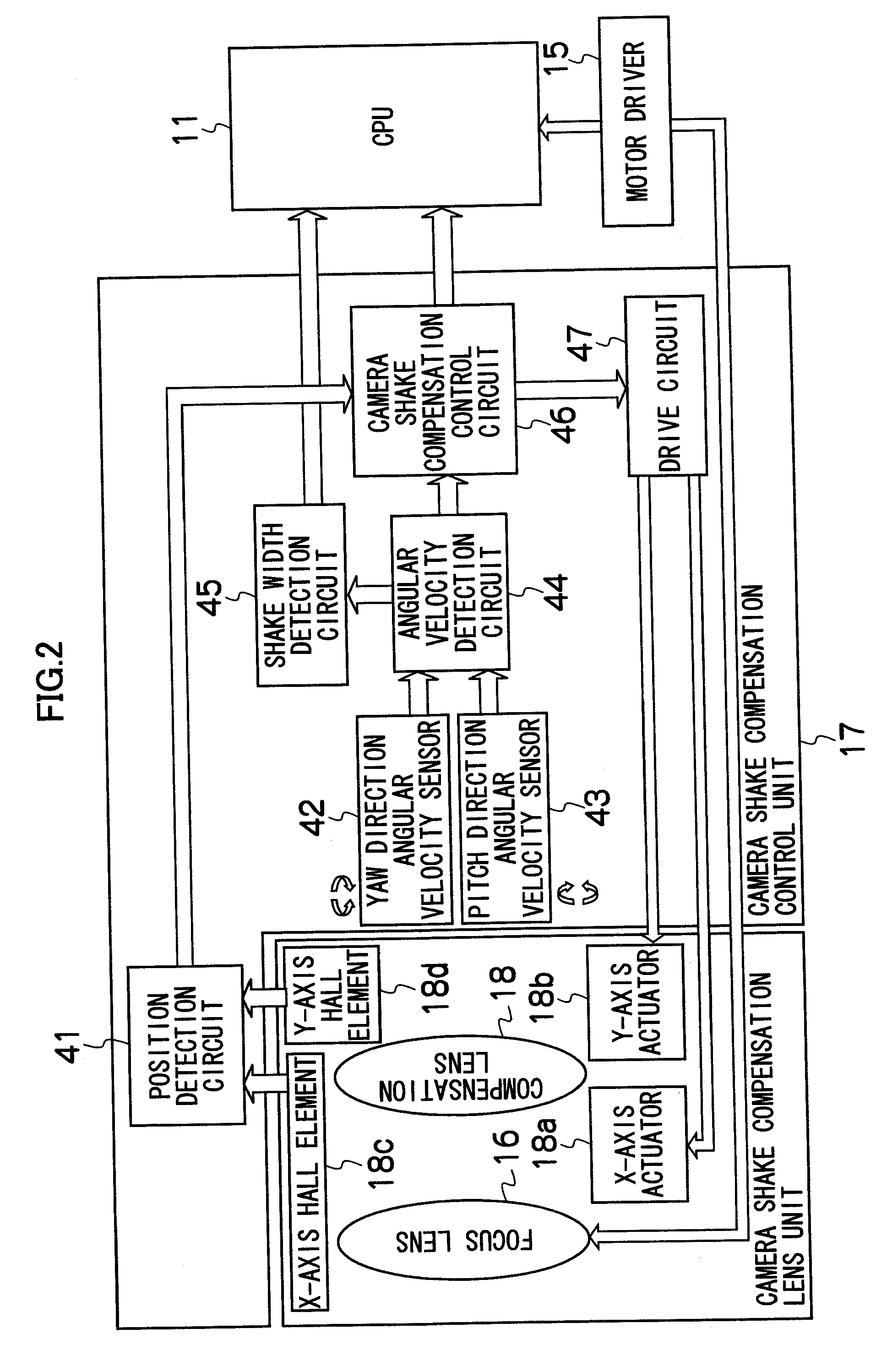
The power consumption is reduced by efficiently using C-AF (continuous autofocus). An angular velocity detection circuit calculates angular velocity based on output from a yaw direction angular velocity sensor and a pitch direction angular velocity sensor. Based on the angular velocity, a shake width detection circuit 45 continuously detects the shake amount of the apparatus. If the maximum value of the shake amount during the latest Nms (N milli-seconds) is less than a pre-determined value, it is judged to be a time for shooting operation and the C-AF is operated. If the maximum value of the shake width during the latest Nms is the pre-determined amount or more, it is judged that shooting operation is not being performed and the C-AF is stopped. In this manner, the power consumption can be reduced by operating the C-AF only as needed.

Description

BACKGROUND OF THE INVENTION[0001]1. Field of the Invention[0002]The present invention relates to an image taking apparatus and an image taking method, and particularly to an image taking apparatus and an image taking method which detect camera shakes and control operation or non-operation of continuous AF.[0003]2. Description of the Related Art[0004]As an autofocus (AF) camera such as a digital camera, a camera is known which can switch between two modes of a so-called single AF mode (S-AF mode) to perform AF operation only if a release button is pressed halfway and retain the focusing state till the half pressing is cancelled after the camera once focused, and a so-called continuous AF mode (C-AF mode) to always perform the AF operation continually and repeatedly irrespective of the half pressing. In the C-AF mode, when a focal point evaluation value decreases after the focusing, the AF operation is started again, a focus lens is moved by a pre-determined amount, focal point evalua...

Claims


Application Information

Patent Timeline
IPC IPC(8): G03B17/00
CPCG03B7/26
Inventor PAN, YIAYAKI, KENICHIRO
Owner FUJIFILM CORP
Learn More