Apparatus and method of optical compensation for submarine optical cable

a submarine optical cable and optical compensation technology, applied in the field of optical transmission technologies, can solve the problems of difficult realization of pre-equalization functions, inflexible configuration, complicated control, etc., and achieve the effects of flexible wavelength configuration, simplified control of dummy light, and reduced power of dummy light signals

Inactive Publication Date: 2008-12-18
HUAWEI TECH CO LTD
View PDF16 Cites 35 Cited by
  • Summary
  • Abstract
  • Description
  • Claims
  • Application Information

AI Technical Summary

Benefits of technology

[0019]In embodiments of the present invention, optical compensation is performed by using a channelized dummy light signal generated according to a continuous spectrum or a continuous dummy light signal generated by blocking wavelengths corresponding to service signals. When the service signals are increased, the adjustment for the power of the dummy light signal is avoided; therefore, the control for the dummy light is simplified. In the pre-equalization operation, power control is only performed on the dummy light signal in the single channel or the continuous dummy light signal; therefore, the realization of the pre-equalization function is easy.
[0020]In addition, the optical power of the dummy light signal in the single channel or the continuous dummy light signal is correspondingly low, the system is not influenced by the nonlinear effect; therefore, the configuration of the wavelengths is flexible.

Problems solved by technology

The conventional problems include complicated control, difficult realization of the pre-equalization function and inflexible configuration.

Method used


Image

  • Apparatus and method of optical compensation for submarine optical cable
  • Apparatus and method of optical compensation for submarine optical cable
  • Apparatus and method of optical compensation for submarine optical cable

Examples


first embodiment

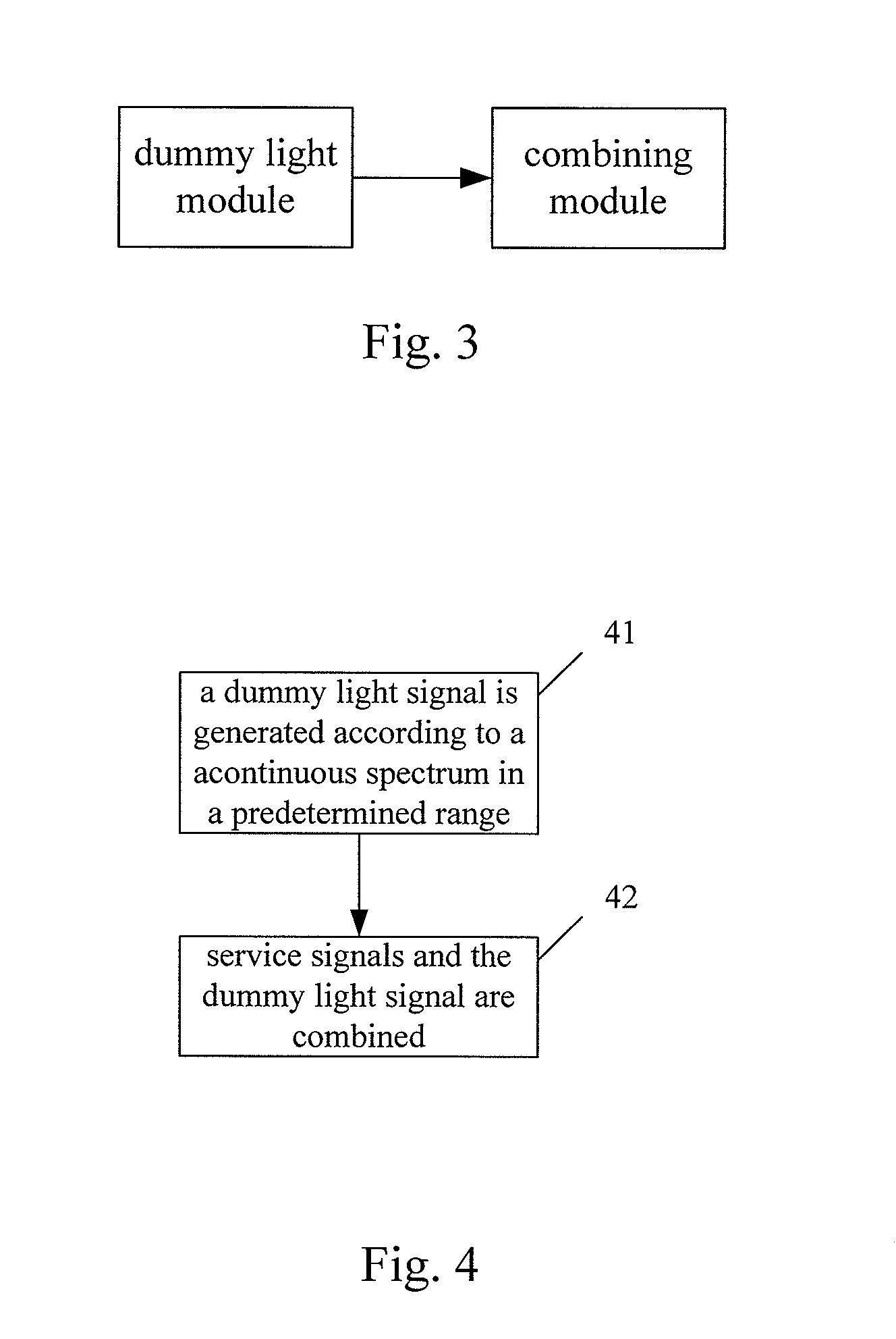
[0037]FIG. 3 is a schematic illustrating a structure of an apparatus of optical compensation for a submarine optical cable according to the present invention. As shown in FIG. 3, an apparatus of optical compensation for a submarine optical cable provided by the present invention includes a dummy light module and a combining module.

[0038]The dummy light module is configured to generate a dummy light signal according to a continuous spectrum.

[0039]The combining module is configured to combine a service signal with the dummy light signal generated by the dummy light module.

[0040]The combining module performs optical compensation for the service signal by combining the service signal with the dummy light signal.

second embodiment

[0041]FIG. 4 is a flowchart illustrating a method of optical compensation for a submarine optical cable according to the present invention. As shown in FIG. 4, the method of optical compensation for a submarine optical cable includes the following processes.

[0042]At block 41, a dummy light signal is generated according to a continuous spectrum in a predetermined range.

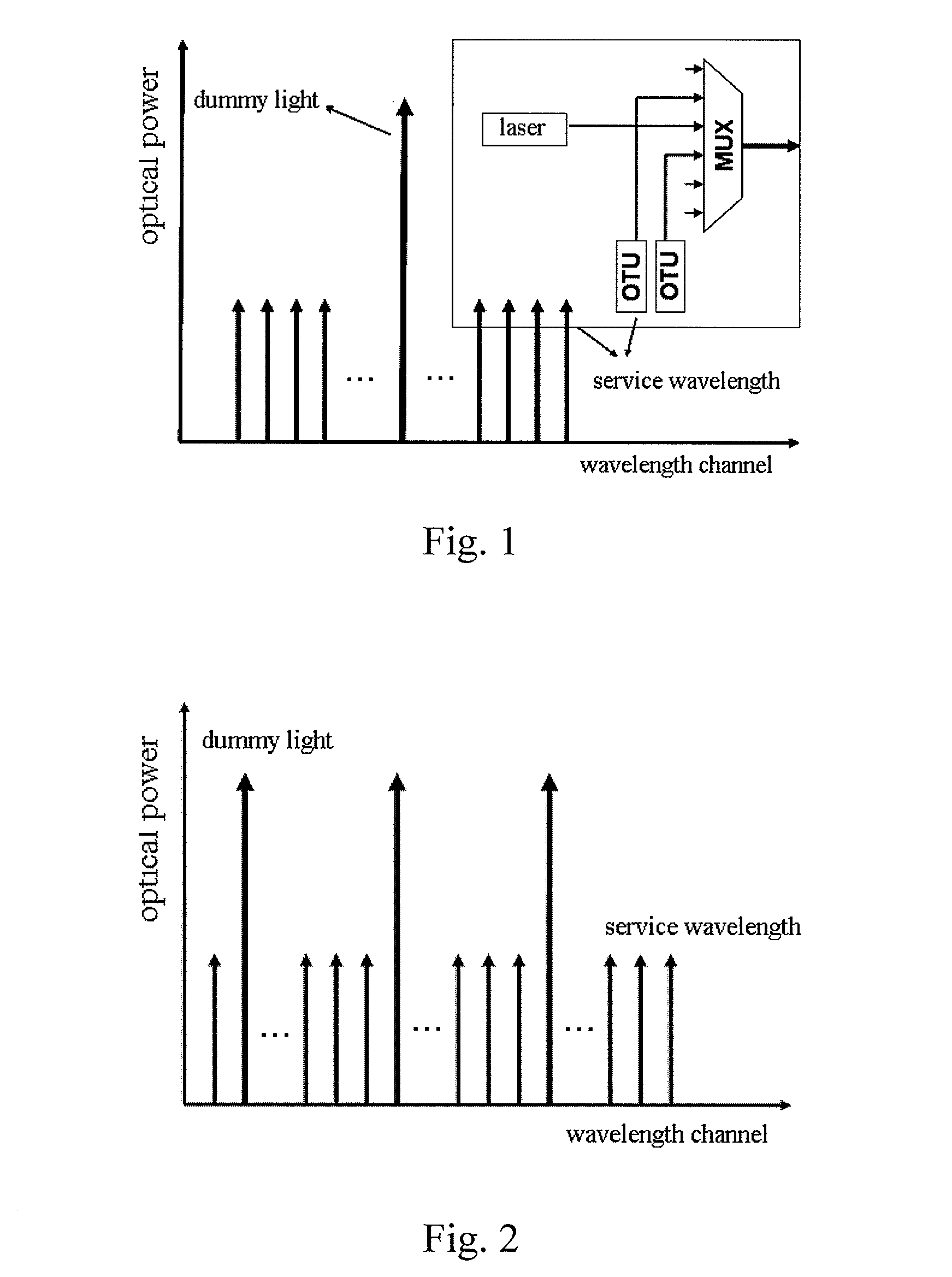
[0043]In the embodiment of the present invention, the continuous spectrum in the predetermined range may be filtered to generate a channelized dummy light signal, or a wavelength corresponding to a service signal in the continuous spectrum in the predetermined range may be blocked to generate a continuous dummy light signal.

[0044]When the channelized dummy light signal is generated, the channel corresponding to the dummy light signal may be different from the channel corresponding to the service signal after the filtration is performed; or the number of dummy light signals may correspond to the number of channels in a ...

third embodiment

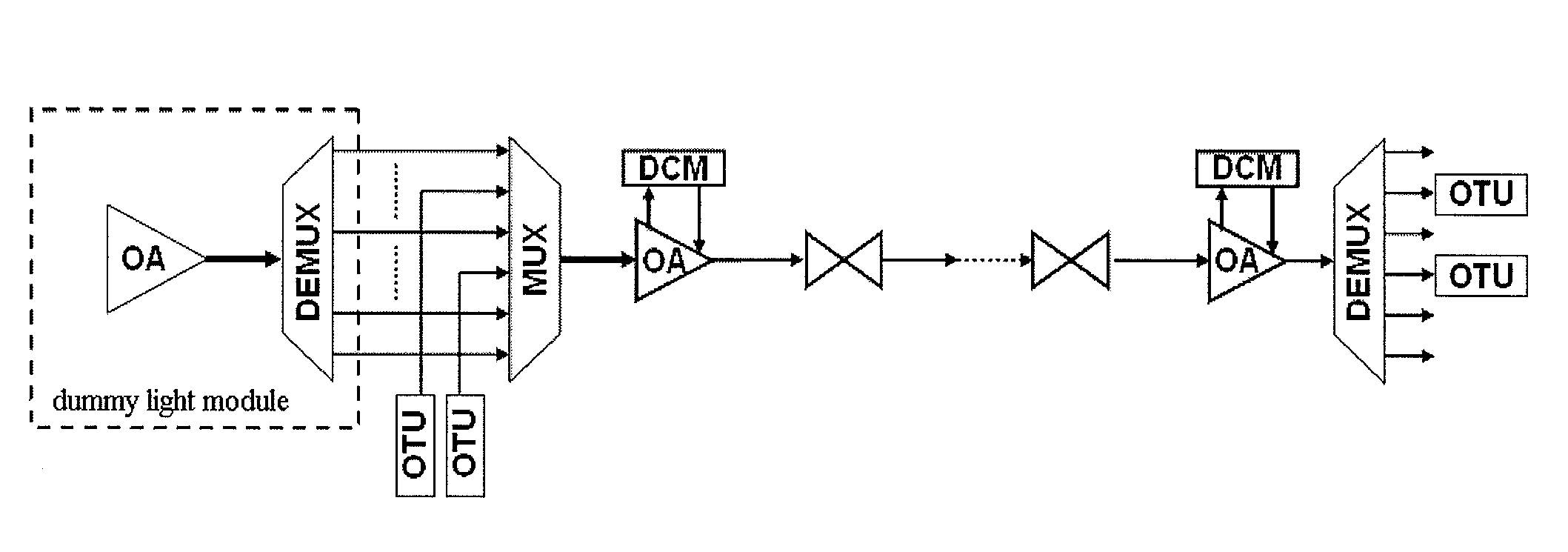
[0049]FIG. 5 is a schematic illustrating a structure of an apparatus of optical compensation for a submarine optical cable according to the present invention. In the embodiment, the dummy light module includes a continuous spectrum generating unit and a filtering unit. The continuous spectrum generating unit is an Optical Amplifier (OA), the filtering unit is an optical De-multiplexer (DEMUX), and the combining module is an MUX.

[0050]As shown in FIG. 5, the apparatus in the embodiment is described below.

[0051]The OA is configured to output Amplified Spontaneous Emission (ASE) noise light when an EDFA is pumped without any input, i.e. generate an optical signal working in the C waveband as the continuous spectrum.

[0052]The DEMUX is configured to filter the ASE noise light output by the OA, and select a channel without the service signal as a dummy light channel. In this way, the ASE noise light is split into channelized dummy light.

[0053]The MUX is configured to combine the service s...


PUM


Abstract

The present invention provides optical compensation for a submarine optical cable optical. A dummy light module generates a dummy light signal according to a continuous spectrum in a predetermined range and a combining module combines a service signal with the dummy light signal. When the dummy light is used for the compensation, conventional problems are solved, including complicated control, difficult realization of the pre-equalization function and inflexible configuration. When service signals are increased, the adjustment for the power of the dummy light signal is avoided; therefore, the control for the dummy light is simplified. In the pre-equalization operation, power control is only performed on the dummy light signal in the single channel or the continuous dummy light signal; therefore, the realization of the pre-equalization function is easy.

Description

CROSS-REFERENCE TO RELATED APPLICATIONS[0001]This application claims priority to Chinese Patent Application No. 200710065287.6, filed Apr. 10, 2007, which is hereby incorporated by reference in its entirety.FIELD OF THE INVENTION[0002]The present invention relates to optical transmission technologies, and more particularly, to an apparatus and method of optical compensation for a submarine optical cable.BACKGROUND OF THE INVENTION[0003]Along with the rapid development of information technologies, submarine optical cables bearing important international communication services have covered large sea areas on the earth. Submarine optical systems are usually divided into two categories: short distance systems without relay, and medium and long distance systems with relay. Equipment in the medium and long distance system includes Network Protection Equipment (NPE), Submarine Line Terminal Equipment (SLTE), Power Feeding Equipment (PFE), Line Monitoring Equipment (LME), optical amplifier ...

Claims


Application Information

Patent Timeline
Patent Type & Authority Applications(United States)
IPC IPC(8): H04B10/00H04B10/296
CPCH04B10/296H04J14/021H04J14/0221
Inventor LU, YIQUANLI, CONGQILI, SHANFENG
Owner HUAWEI TECH CO LTD
Why Eureka
Try Eureka