Apparatus and Methods for Fastening a Panel or Other Components

a technology for fixing panels and other parts, applied in the field of fixing screws, can solve the problems of affecting the performance of the clamp nuts, requiring relatively significant assembly and installation time, and not having the strength to reliably secure and maintain the nuts under high loads, etc., to achieve the effect of easy assembly, high load capacity and convenient maintenan

Active Publication Date: 2008-12-18
MONADNOCK
View PDF61 Cites 62 Cited by
  • Summary
  • Abstract
  • Description
  • Claims
  • Application Information

AI Technical Summary

Benefits of technology

[0006]Fastener assemblies can be made that are lightweight, easy to assemble, and / or have a high load capability. A fastener assembly can also be made such that it is easier to maintain, as well as to allow easier maintenance of hardware secured by the fastener assembly. In one example of a fastener assembly, for example a nut assembly, a nut includes a plurality of projections, any one of which make the perimeter of the nut non-circular. The nut is supported by a nut support with one or more surfaces to be engaged by and which may be complementary to corresponding ones of the plurality of projections on the nut. The nut support surfaces engaging a projection on the nut limits or prevents rotation or pivoting of the nut relative to the support. In one configuration, the nut is allowed to float axially of a threaded bore of the nut a selected distance suitable for the application. The complementary surfaces on the nut support engage corresponding surfaces on respective projections on the nut to limit pivoting of the nut about its axis. As a result, the complementary surfaces on the nut support bear any loading that may occur during torque of the nut. The nut may be captured by a cage formed as part of the nut support, for example so that the complementary surfaces limit or prevent pivoting of the nut relative to the cage. The configuration of the cage may permit the desired float and provide the bearing surfaces that bear the loading from torquing from the nut.
[0014]Another example of a clip may include a non-metal clip having opposed first and second arms joined at respective first ends of the arms. The arms may include openings for receiving a fastener for engaging a nut element. The third portion spaced apart from the second arm on a side of the second arm opposite the first arm joins the second arm through a transition wall. The third portion includes width-wise side edge surfaces and at least a first edge surface extends over the corresponding portion of the second arm and is sufficiently disconnected from the second arm to allow the first edge surface to flex toward and away from the second arm. The third portion and the second arm may form part of a nut cage and flexing of the first edge surface may make easier the installation of a nut element in the clip. The clip may include one or more bearing surfaces against which a corresponding element or elements on the nut element may bear when the nut element is under torque. The bearing surfaces may be the same as or similar to any of the bearing surfaces described herein against which a portion of a nut element bears.
[0015]In another example described herein, a method for forming a clip for a clip nut assembly includes forming a monolithic clip and nut cage combination, for example from a non-metal material. The combination is formed so as to have a cantilever wall portion that can flex toward and away from the rest of the clip. The cantilever wall portion allows easier installation of the nut element into the cage portion of the combination. The combination can be formed through molding, for example. In one example, the combination is formed so that the cantilever wall portion has a width-wise common transition wall with the rest of the clip with the rest of the cantilever wall portion disconnected from the clip. Forming the clip in this way allows a significant flexing of the cantilever wall portion for inserting the nut element. In one example, the cantilever wall portion is molded to include an opening configured to conform to the outer profile of a nut element barrel, and may include a press-fit gap similar to that described in U.S. Pat. No. 6,854,941. In another example, the combination can be molded or otherwise formed to include one or more bearing surfaces against which complementary portions of the nut element can bear while the nut element is under torque.

Problems solved by technology

Depending on the configuration, some clip nuts can mar the panel, for example on installation or during normal use.
Some may also require relatively significant assembly and installation time, and some may not have sufficient strength to reliably secure and maintain the nut under high loads.

Method used


Image

  • Apparatus and Methods for Fastening a Panel or Other Components
  • Apparatus and Methods for Fastening a Panel or Other Components
  • Apparatus and Methods for Fastening a Panel or Other Components

Examples


Embodiment Construction

[0065]This specification taken in conjunction with the drawings sets forth examples of apparatus and methods incorporating one or more aspects of the present inventions in such a manner that any person skilled in the art can make and use the inventions. The examples provide the best modes contemplated for carrying out the inventions, although it should be understood that various modifications can be accomplished within the parameters of the present inventions.

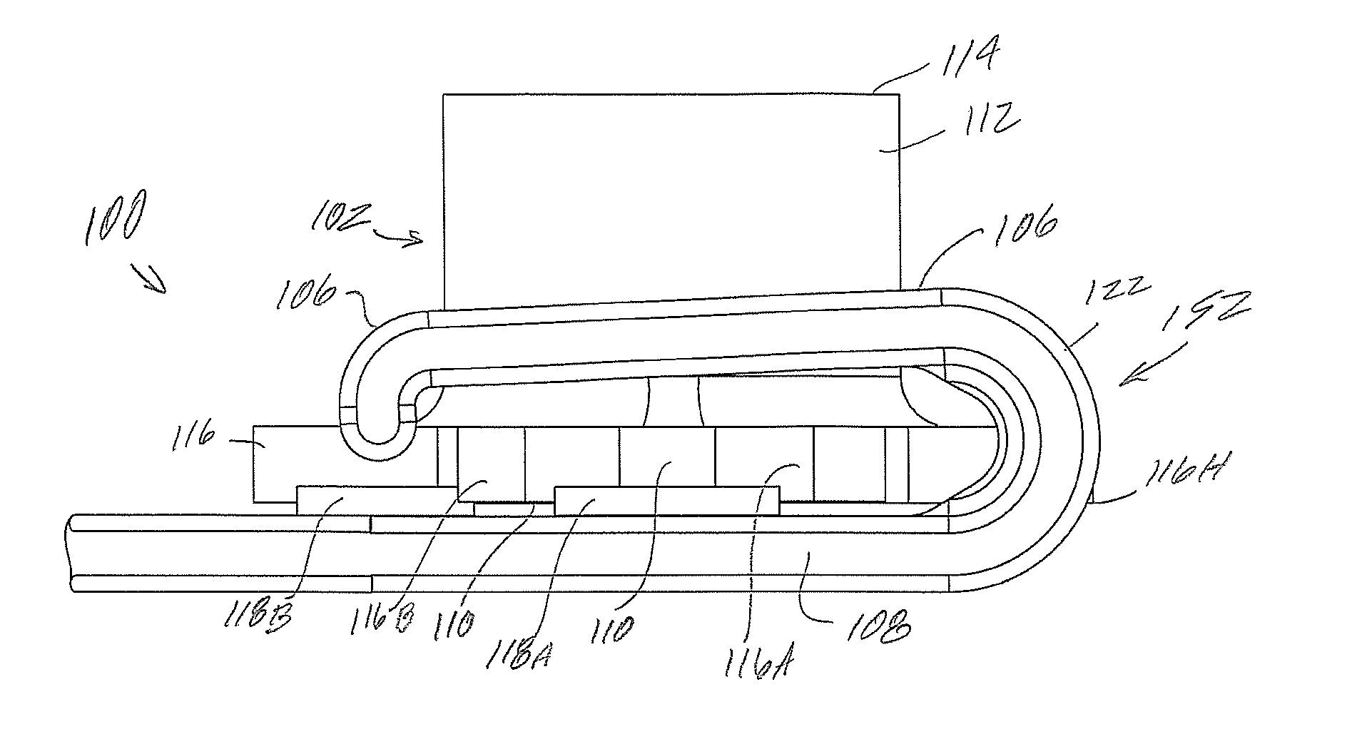
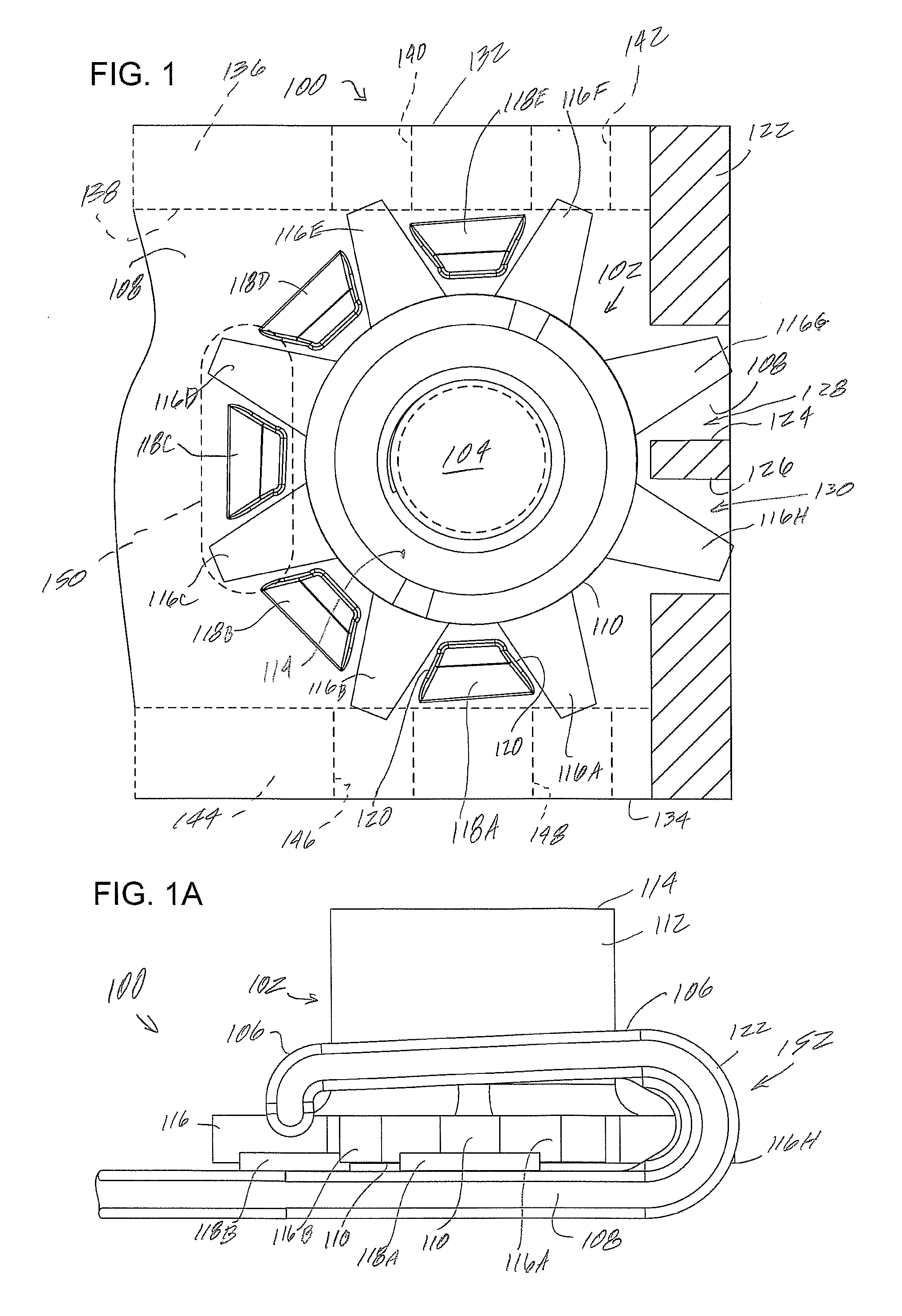
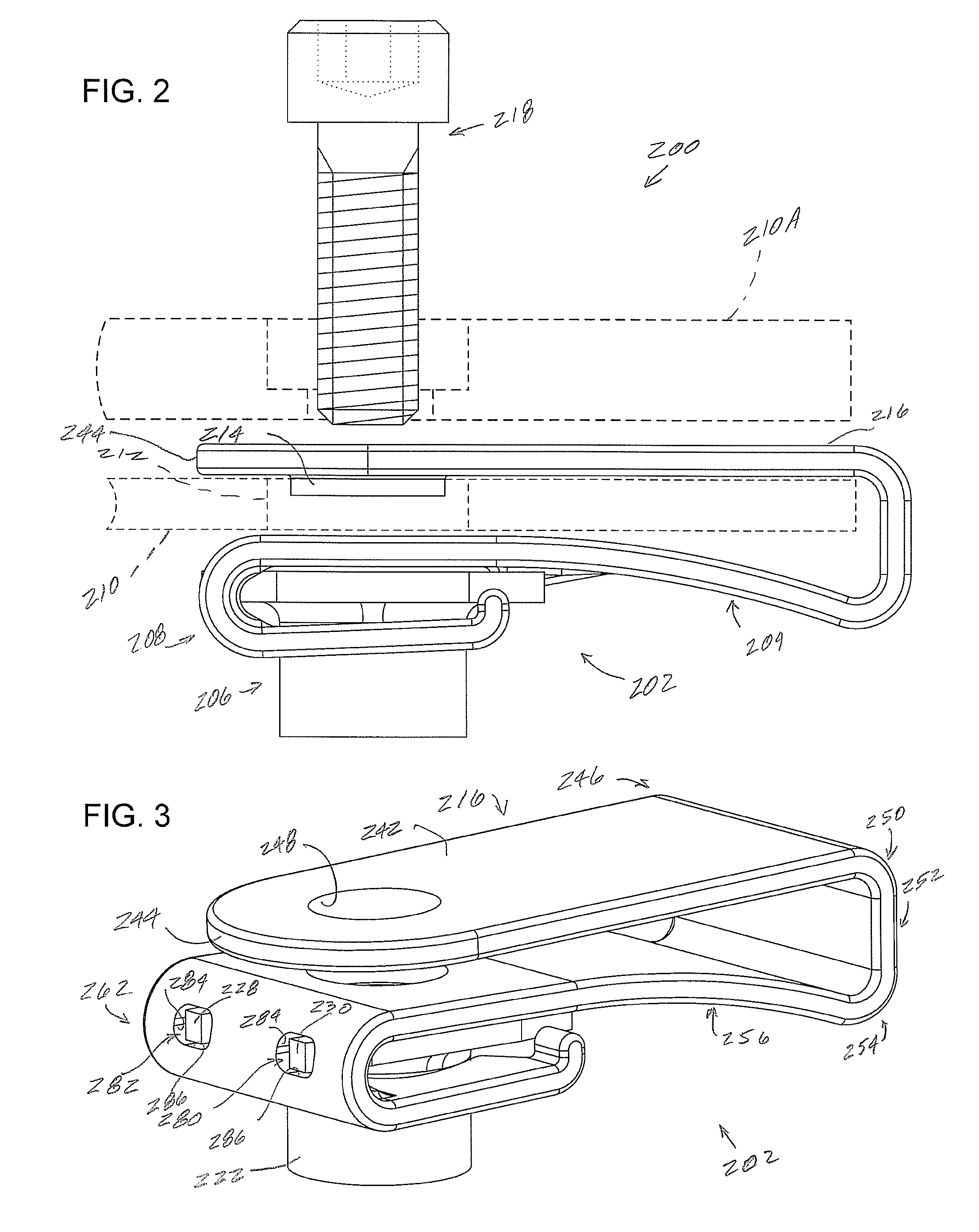
[0066]Examples of fastener assemblies and of methods of making and using the fastener assemblies are described. Depending on what feature or features are incorporated in a given structure or a given method, benefits can be achieved in the structure or the method. For example, fastener assemblies with a nut element held in a nut cage having a flexible element may be easier to use and maintain. Fastener assemblies with nut elements having a larger number of bearing surfaces may withstand greater torque forces and may have greater...


PUM

PropertyMeasurementUnit
perimeteraaaaaaaaaa
perimeter areasaaaaaaaaaa
flexibleaaaaaaaaaa

Abstract

Fasteners such as clip nut fasteners can include a clip having a nut cage and a nut supported by the nut cage. The nut cage can have a wall supporting a portion of the nut wherein the wall can flex toward and away from the nut. The nut can have projections or other discontinuities for engaging bearing surfaces in the nut cage, for limiting rotation of the nut when under torque.

Description

BACKGROUND[0001]1. Field[0002]This relates to fasteners, for example clip nut fasteners, nut cages and similar assemblies, methods of forming fasteners, methods of assembling fasteners, methods of securing panels and other components with fasteners and assemblies using such fasteners.[0003]2. Related Art[0004]Clip nuts are typically configured to slide over an edge of a panel to align a nut with a hole formed in the panel. The nut receives a bolt, screw or other threaded element passed through the hole and threaded into the nut. Various such clip nuts may be used to mount items to the panel or for securing panels together. Clip nuts may be used in automobiles, appliances and aircraft, as well as in other applications. Also, a given application may call for a large number of clip nuts. For example, in assembling a single commercial aircraft hundreds of thousands of clip nuts can be used.[0005]Depending on the configuration, some clip nuts can mar the panel, for example on installatio...

Claims


Application Information

Patent Timeline
Patent Type & Authority Applications(United States)
IPC IPC(8): F16B37/04F16B39/24B23P11/00
CPCF16B37/043F16B37/044Y10T29/49947Y10S411/97F16B39/24
Inventor CSIK, TERRENCEKOMSITSKY, IGORREAD, FRANK
Owner MONADNOCK
Why Eureka
Try Eureka